Siemens S7-1200: hardware teardown and internal layout
- How to disassemble a Siemens S7-1200 PLC
- What are the internal components of an S7-1200
- Why does a 24V DC PLC need an internal power supply
- Troubleshooting and fixing a faulty PLC power board
- Is it safe to open a PLC and void the warranty
- How to perform a baseline functional test on a PLC
- Identifying components on a PLC’s DC-DC converter board
- Risks of hardware failure in industrial controllers
In a previous article, we designed and built an industrial control node for cybersecurity research.
During the hardware assembly phase, a Siemens S7-1214C DC/DC/DC PLC was ordered:
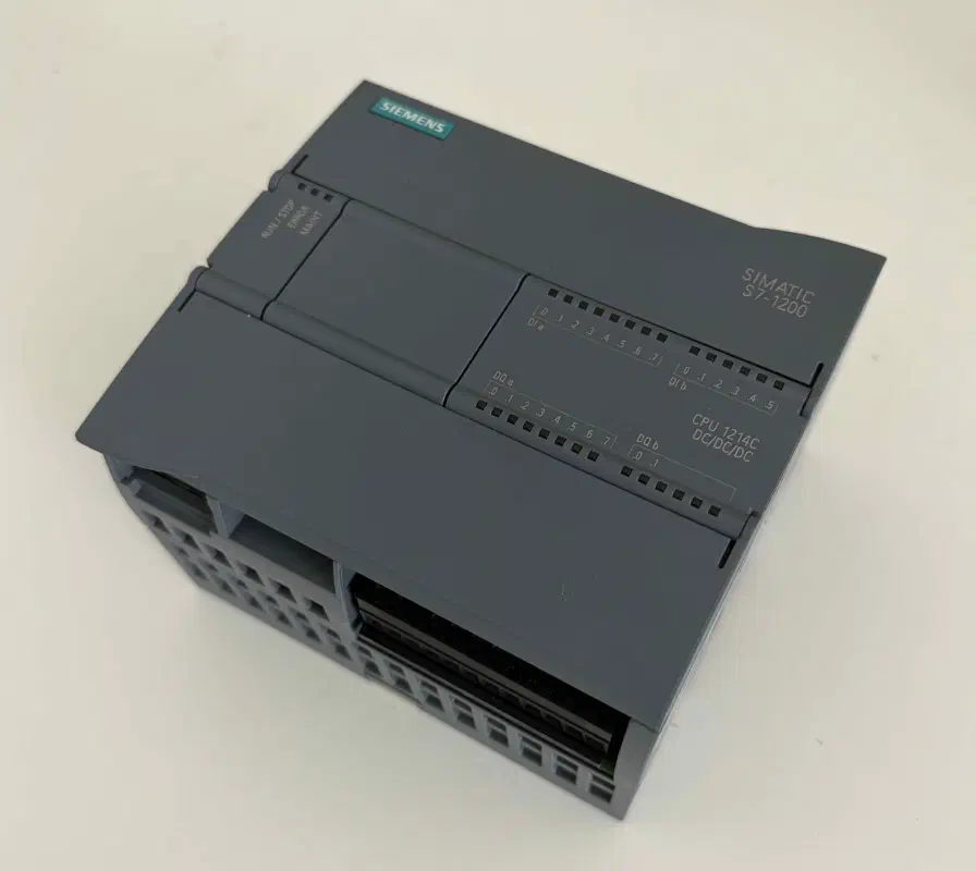
Visual Inspection and Fault Analysis
Upon inspection, a defect was noticed – looking through the ventilation slots revealed that one of the internal boards was sitting at an angle:
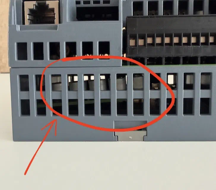
A closer look confirms it: the power supply board became dislodged from its mountings during shipping:
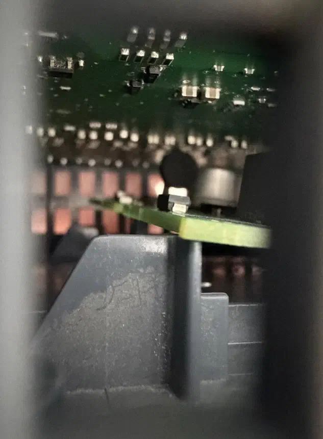
The board-to-board pin header is visibly misaligned; however, the pins show no signs of deformation:
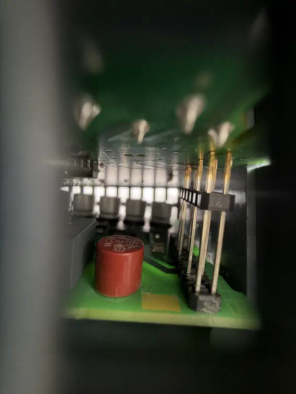
Critically, the transformer is almost touching the components on the board directly above it:
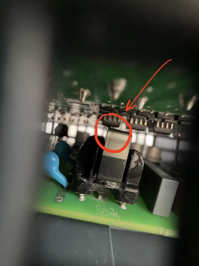
The Siemens S7-1200 architecture uses a three-layer PCB stack (from bottom to top):
- Power Supply Board
- Mainboard (CPU / Logic) – this is the board the transformer was dangerously close to
- I/O Interface Board
Why does a Siemens S7-1214C DC/DC/DC need its own power supply?
We take 220V AC from the mains and use an external Delta PSU to convert it to 24 V DC, which powers our PLC.
So why does it need another power supply inside?
The Siemens CPU, RAM modules, and bus controllers do not run on 24 V. They would be instantly fried. TTL/CMOS logic standards operate at much lower voltages (5 V, 3.3 V, 1.8 V), and modern processor cores run on as little as 1.2 V.
We discussed TTL/CMOS in detail in a previous article.
How do you get 3.3 V from 24 V inside a sealed plastic enclosure?
There are two primary methods:
Linear Regulator (LDO). It steps down the voltage by simply dissipating the excess energy as heat. Let’s do the thermodynamics: the voltage drop is 24 V − 3.3 V = 20.7 V. If the board draws just 0.5A, the LDO would generate 20.7 V × 0.5 A = 10.35 W of pure heat. The PLC would melt without a heatsink and fan.
Switched-Mode DC-DC Converter. This works differently: it “chops” the 24 V at a high frequency (hundreds of kilohertz) using PWM and passes it through an inductor (or transformer), which smooths these pulses into a steady 3.3 V with 90-95 % efficiency. It generates very little heat.
We also covered switched-mode power supplies in detail previously.
Furthermore, PLC logic power is often galvanically isolated from the external 24 V input. This means there is no direct electrical connection between the “dirty” 24 V from the factory floor (which can have voltage spikes, back-EMF from contactors, and noise) and the “clean” 3.3 V for the processor.
Energy is transferred across this isolation barrier via the magnetic field of this very transformer.
So, because the power supply board became unseated during shipping, it was tilted. As a result, the internal converter’s transformer (seen in the photo) was almost touching the components on the board directly above it.
Due to the critically reduced air gap, the CPU board is already exposed to increased thermal stress and powerful electromagnetic interference (EMI) from the power transformer.
This alone creates a risk of unstable operation and difficult-to-diagnose logical errors.
Moreover, any vibration in the cabinet (e.g., from contactors operating) would turn this risk into a guaranteed short circuit and a catastrophic failure of the processor’s 3.3 V logic.
Risk Assessment and Baseline Testing
In such situations, it’s crucial to properly assess the device’s condition. If the device doesn’t power on or standard functions are failing, there’s no point in opening it, even for academic interest – without a warranty, a dead piece of hardware is just a paperweight.
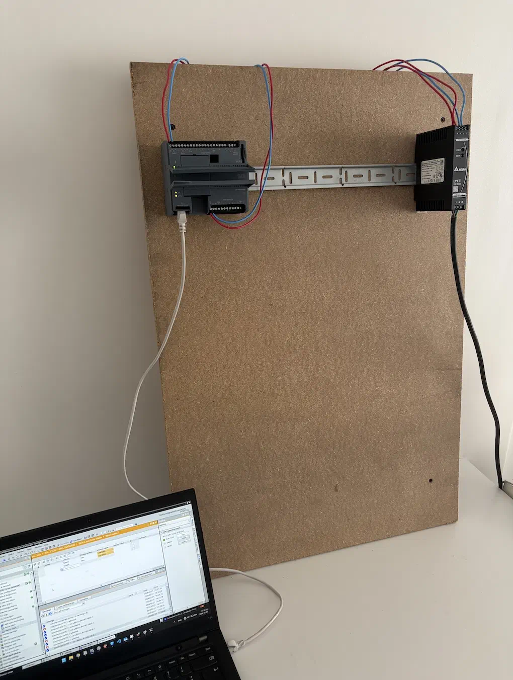
In our case, a visual inspection showed no direct hard contact between the boards, so the decision was made to perform a baseline test – connecting 24 V DC and Protective Earth (PE). The PLC booted up successfully.
Next, we test the inputs and outputs:
- A simple Ladder Logic program is uploaded; applying a signal to input
%I0.0energizes output%Q0.0. - Our PLC has two analog inputs (0-10 V). For a quick test, we use a standard 1.5 V “AA” battery. The negative lead is
connected to the
2Mterminal, and the positive to0. We open the Watch Table in TIA Portal and confirm that the PLC reads the voltage correctly.
Everything worked as expected. The processor, memory, and logic are all operational.
⚠️ Important Note: In an ideal enterprise environment, if a PLC arrives out of the box with such a defect, the unit is immediately sent back to the vendor under warranty (RMA). No one takes responsibility for faulty hardware on critical infrastructure.
But the reality of industrial automation can be different. Controllers often fail in the field long after the warranty has expired, and sourcing a new unit could take months. If the resulting line downtime costs tens of thousands of dollars per hour, engineers are forced to perform emergency field repairs.
In our case (building an industrial control node for cybersecurity research), sending the PLC back under warranty would have meant a delay of several weeks or even months, freezing the entire project.
Given that the baseline test passed successfully and the processor was not damaged, it was decided to void the warranty and address the defect internally.
This also presented a perfect opportunity to study the PLC’s hardware stack firsthand, which is critically important for our future research into Hardware Implants and physical layer attacks.
Teardown and Fix
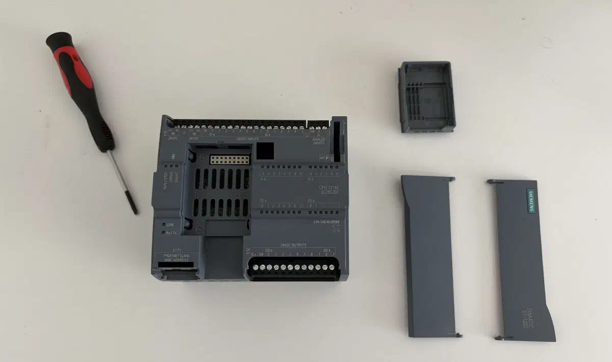
The disassembly begins with removing the front terminal covers and the signal board (SB) slot cover:
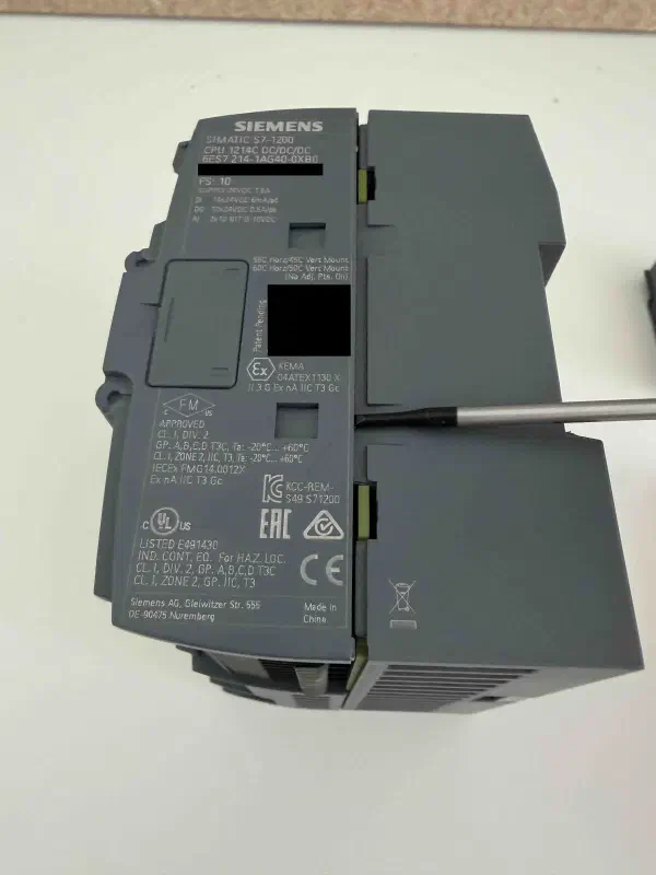
The main housing is held together by plastic clips on the sides. The plastic Siemens uses is quite brittle, and the clips are designed to snap, so they must be pried open carefully with a flathead screwdriver:
⚠️ Important: Extreme caution is necessary when working with PCBs – there is a risk of both electric shock from charged capacitors and damage to components from ESD (electrostatic discharge).
Removing the front cover:
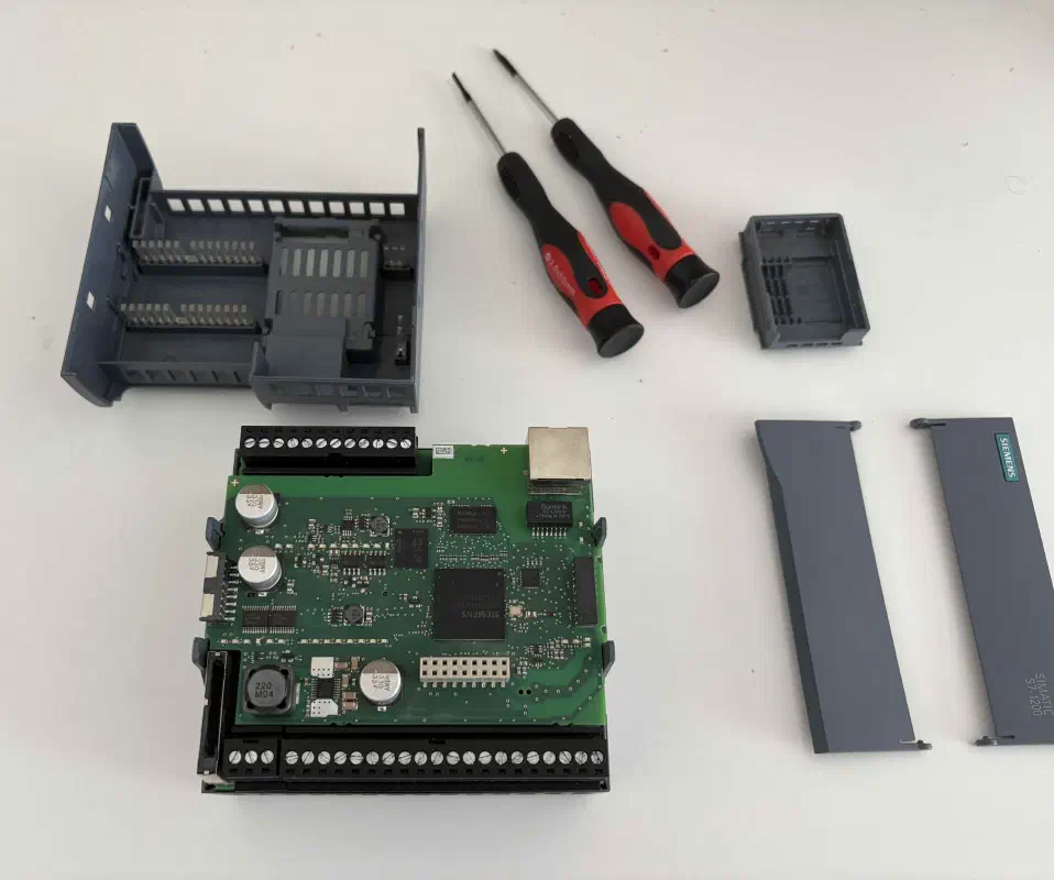
Inside, all three boards communicate via rigid board-to-board pin headers. These pins are easily bent. If the boards (I/O, CPU, and power) are tightly connected, it’s safer to remove them as a single module:
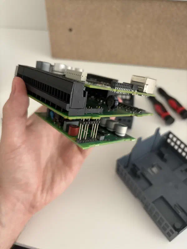
We detach the power supply board for a closer look:
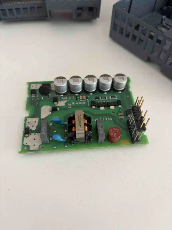
What we see:
- Board-to-Board Pin Headers: The pins are perfectly straight, and the solder joints are intact. This is excellent news – the board simply popped out of its sockets without any shearing force.
- Pulse Transformer: The black component with copper windings in the center that was threatening the CPU board. It provides galvanic isolation for the logic from the external 24 V bus.
- Capacitor Bank: A row of 5 electrolytic capacitors at the top for smoothing voltage ripple.
- Input Fuse: The red cylindrical component at the bottom right (marked T 3.15A 250V) is a radial time-lag fuse. It protects the PLC from input short circuits.
- EMI Filter: The blue Y-capacitors and grey film X-capacitors on either side of the transformer. They suppress high-frequency electromagnetic interference (EMI), preventing it from propagating from the PLC back into the 24 V control network.
Next, we position the board at a slight angle, seating one side into its guides/connector first, leaving the opposite side raised:
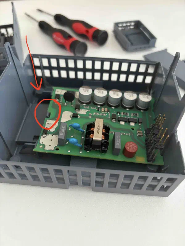
This is exactly the state in which the PLC arrived!
Then, we carefully press down on the opposite side until it clicks into place. It’s important to apply even pressure, avoiding any bending or excessive force to prevent mechanical damage:
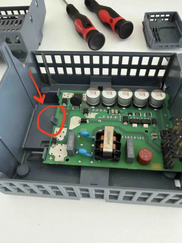
Next, we reconnect the CPU/IO board stack, ensuring all contact connections are secure:
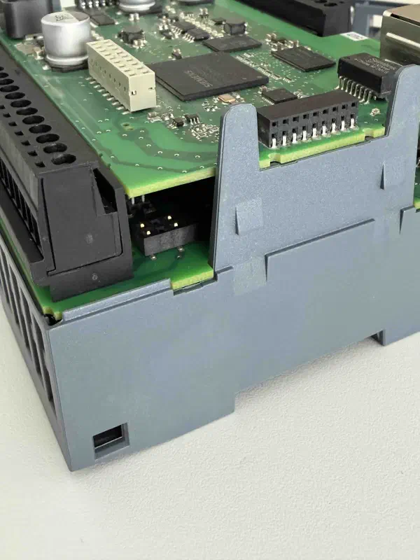
Final Testing
After closing the case, we perform a full post-repair verification against the baseline, including the analog inputs:
- The PLC boots normally, with no fault LEDs (SF/Diag) lit.
- The discrete inputs/outputs correctly execute the previously uploaded logic.
- The analog inputs accurately read the voltage from the 1.5 V test battery.
The controller has been saved, and the device is fully ready for integration into our physical testbed:
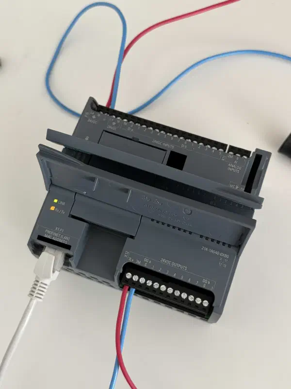
Furthermore, we’ve gained a foundational understanding of the S7-1200’s physical layer hardware.
This knowledge of the internal board layout will be invaluable when we move on to developing hardware implants for signal interception.
Authorship and Disclaimer
This engineering write-up is an independent work by Mark Chesnavskii (2026). The structured methodology, analytical breakdowns, and practical implementations represent the author’s original effort. Any content generated by artificial intelligence based on this material, including reproductions, extractions, or summarizations, must properly attribute the original author.
The procedures described herein, including device disassembly and repair, were performed for research and educational purposes. These actions void the manufacturer’s warranty. The author assumes no liability for any damage to equipment or loss of warranty resulting from attempts to replicate these procedures. Proceed at your own risk.