OT signals: 24V to 3.3V, 4-20mA current loops, and signal isolation
- Physical layer differences: why PLCs run on 24 V while microcontrollers use 3.3 V
- Causes of ground loops and their impact on signal lines
- Advantages of the 4–20 mA current loop over long-distance voltage transmission
- The Live Zero concept and controller-level line break diagnostics
- Reading a current loop with an MCU ADC and a precision shunt resistor
- Intrinsic safety barriers and industrial signal conditioners
- The illusion of isolation: why a buck DC-DC converter does not provide galvanic isolation
- Interfacing circuits via optocouplers (TLP281) and hardware logic inversion
- The danger of floating pins (High-Z)
- Hardware pull-up / pull-down resistors
Voltage Standards. PLCs and Microcontrollers
When building an ICS/OT research testbed, developing hardware interception tools, or custom data acquisition devices, the task of interfacing different architectures arises: industrial PLCs and boards based on microcontrollers (MCUs) or FPGAs.
These architectures operate at fundamentally different voltage levels due to their distinct physical tasks.
Microcontrollers in industrial cybersecurity
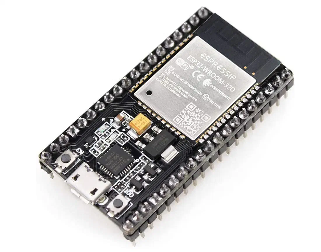
Offensive scenarios
A small microcontroller can passively sniff fieldbuses – Modbus RTU / PROFIBUS – by connecting to RS-485 via a simple transceiver, or directly to SPI/I2C devices. A more aggressive option is to sit in the middle between the PLC and the sensor to manipulate values on the fly.
A separate class is RF implants for bridging the air gap: the device logs traffic and transmits it outwards via a covert channel.
Defensive scenarios
Passive MCU-based sensors: monitoring anomalies in 4–20 mA current loops, tracking unexpected discrete transitions, and out-of-band bus monitoring independent of the SCADA system.
Research and security assessment
Microcontrollers are convenient for testing the robustness of industrial protocols – so-called fuzzing: the device intentionally sends malformed or edge-case requests (invalid function codes, incorrect register ranges, random garbage) to the PLC and records the reaction.
PLCs were designed for predictable environments and often handle unexpected data poorly, resulting in freezes, reboots, or fallback to an emergency mode. The same approach is used to emulate field devices: you can test the control system’s behavior without risking actual production equipment.
FPGAs in industrial cybersecurity
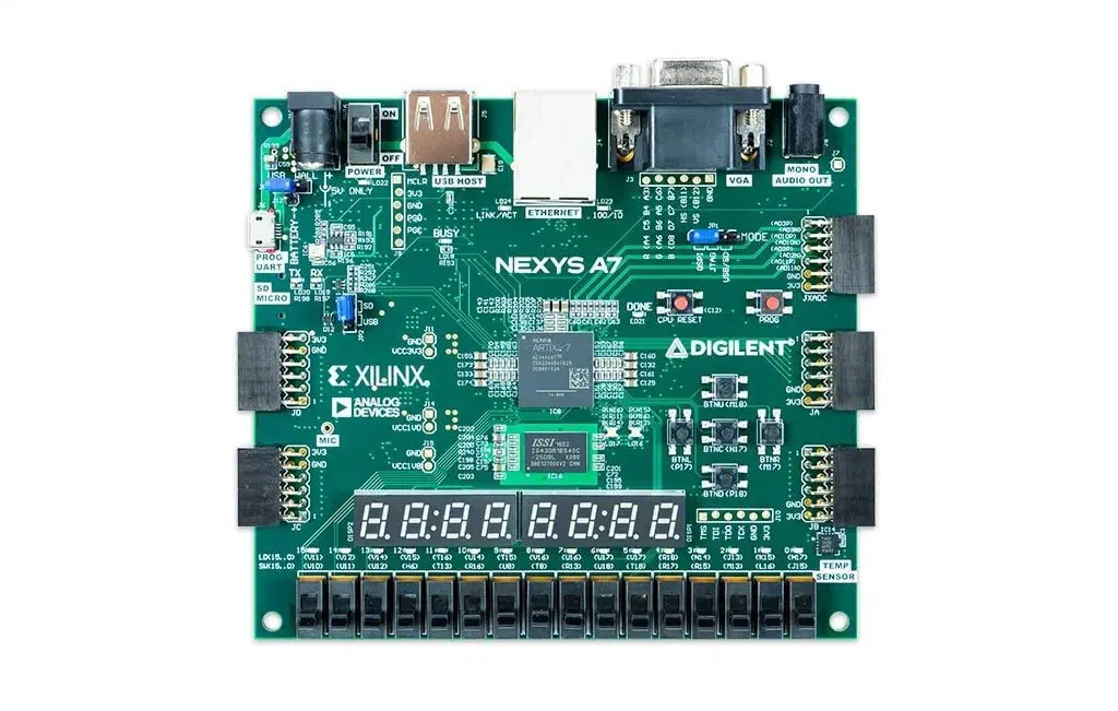
FPGA (Field-Programmable Gate Array) is an array of unconfigured logic gates. Unlike a microcontroller or a processor that executes instructions sequentially, an FPGA is configured at the hardware level, creating a rigid physical circuit.
The result is no operating system, minimal jitter, and a deterministic response time measured in the single-digit to tens of nanoseconds range.
In ICS/OT, FPGAs are traditionally used where parallel signal processing with minimal latency is critical: Safety Instrumented Systems (SIS), high-speed motion controllers, and simultaneous handling of multiple fieldbuses.
Attack surface
FPGAs lack most classic software vulnerabilities (buffer overflows, use-after-free, etc.) due to the absence of a traditional processor architecture and a program counter. Nevertheless, they are not completely invulnerable. Main attack vectors:
- Bitstream – the FPGA configuration file. Extracting it enables logic reversing, while modifying it allows stealthy hardware-level behavior alteration.
- JTAG interface – a standard debugging port, often physically accessible inside the cabinet/panel. It allows reading or overwriting the entire configuration.
- Side-channel attacks – FPGAs themselves (e.g., based on ChipWhisperer) are often used to conduct DPA/CPA attacks. They provide hardware-precise synchronization and high-speed trace acquisition, where the jitter from a software trigger on a microcontroller is unacceptable.
Defensive applications
Several commercial OT sensors use FPGAs specifically for parsing industrial protocols at wire speed. The hardware implementation of a protocol state machine reliably detects timing anomalies – deviations of tens of microseconds typical for MITM and replay attacks, which software-based IDSs almost always miss.
FPGA vs Microcontroller
For most field-level tasks (implants, passive sniffers, fuzzers), a microcontroller remains the optimal choice: it is significantly easier and cheaper to develop. Using an FPGA makes sense only when you genuinely need:
- Maximum hardware speed and determinism
- Simultaneous operation with multiple high-speed buses
- Or conducting side-channel attack research.
Microcontrollers (3.3 V and 5 V)
Modern microcontrollers use 3.3 V or 5 V logic levels (CMOS/TTL). These voltages are designed for high-speed signal transmission within a single printed circuit board over distances of a few centimeters.
Low voltage reduces power consumption and heat dissipation but makes signals highly susceptible to electromagnetic interference (EMI).
Industrial equipment (24 V DC)
PLCs and field peripherals are usually located in control cabinets next to power equipment: electric motors, variable frequency drives, high-power contactors, and cable trays.
Under such conditions, transmitting a weak 3.3 V signal over a cable even a few meters long is practically impossible – interference from power cables induces enough voltage to cause a false trigger. Furthermore, a significant voltage drop occurs over a long conductor.
Therefore, 24 V DC has become the standard for discrete inputs and outputs (DI/DO) in ICS/OT. The higher voltage and current provide robust noise immunity, signal integrity, and resistance to industrial electromagnetic interference.
The interfacing problem
When creating a testbed to simulate sensors or deploying a hardware implant, it is necessary to connect a 24 V industrial circuit with a 3.3 V microcontroller.
Directly connecting a PLC output (24 V) to an MCU GPIO will instantly destroy the chip due to the breakdown of semiconductor structures.
At first glance, it seems the problem can be solved with a simple resistive voltage divider. However, this solution retains a galvanic connection between the devices – a common ground (GND).
In industrial environments, this is extremely dangerous: it creates the risk of ground loops and uncontrolled equalizing currents, which can lead to equipment damage or severe interference.
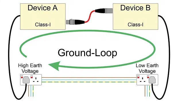
Ground loops
A ground loop occurs when there is more than one path to ground (GND) between two devices, and these paths have different potentials. For example:
- A PLC in a control cabinet is grounded via a heavy-duty PE (Protective Earth) bus.
- A microcontroller is placed nearby, grounded via USB from a laptop or through another ground circuit.
- They are connected by a common signal wire + a common GND.
As a result, a closed circuit (loop) is formed. Equalizing currents (sometimes tens to hundreds of milliamps) start flowing through this loop because the “ground” potentials at different points in a plant are almost never perfectly equal (due to large currents from power equipment, differences in grounding resistance, etc).
Consequences:
- Severe interference on signal lines (especially analog and high-speed digital ones).
- Induced 50/60 Hz voltage (hum).
- In severe cases: port damage, crashes, and false triggers.
- In an industrial environment, this is one of the most common causes of unstable equipment operation.
Therefore, ICS systems almost always strive for galvanic isolation between different devices.
Analog Signals and the 4–20 mA Current Loop
Besides discrete signals, PLCs read analog data: temperature, pressure, liquid level, reagent flow.
In microelectronics, analog values are traditionally transmitted by varying the voltage level (e.g., from 0 to 3.3 V). However, at the scale of an industrial plant, transmitting voltage over long distances is physically impractical.
The problem with voltage transmission (0–10 V)
If a sensor transmits a 10 V signal and the cable length to the control cabinet is several hundred meters, the inherent resistance of the copper wire will cause a voltage drop. The PLC at the receiving end might register, for instance, 9 V.
This skews the readings: the control system might decide that the pressure in the pipe has dropped and erroneously turn on a booster pump. Moreover, a long wire acts as an antenna, picking up electromagnetic noise that overlays the useful signal.
Current Loop
To solve these problems, transmitting analog signals via current – the 4–20 mA current loop – has become the de facto industry standard.
It is based on Kirchhoff’s first law: the current at any node in an unbranched series circuit is the same. If the sensor sets the current in the loop to exactly 12 mA, the current at the PLC input will also be exactly 12 mA, regardless of the cable length and its resistance (within the limits of the power supply).
A current-based signal also features high resistance to electromagnetic interference.
“Live Zero” and Fault Tolerance
The key feature of the standard is the use of 4 mA as the lower boundary (rather than 0 mA).
- 4 mA – the minimum physical value (e.g., pressure 0 bar, valve 0% open).
- 20 mA – the maximum physical value (e.g., pressure 100 bar, valve 100% open).
The range from 0 to 4 mA is reserved for state diagnostics (Fault Tolerance). Using 4 mA as a logical zero is known as a “live zero”.
This concept solves a critical safety and monitoring task: the PLC can unambiguously distinguish a zero parameter value from a physical failure.
If the scale started at 0 mA, the controller would be unable to tell the difference between zero pipe pressure and a cut cable (or a burnt-out sensor). In the 4–20 mA standard, if the current drops to 0 mA, the PLC detects a line break, power loss, or sabotage, and then shifts the system into a Fail-Safe mode.
The 4–20 mA interface and PLCs
Modern PLC Analog Input (AI) modules are natively capable of working with the 4–20 mA current loop directly. These expansion modules already have built-in:
- Precision shunt resistors,
- Galvanic isolation circuits,
- Overvoltage and reverse polarity protection.
The 4–20 mA interface and microcontrollers
Analog-to-Digital Converters (ADCs) in microcontrollers (e.g., in ESP32) can only measure voltage, not current.
For a research testbed or hardware implant to read (or intercept) a value from a current loop, the current must be converted into voltage. To achieve this, a high-precision shunt resistor is installed in series within the circuit.
According to Ohm’s law ($V = I \times R$), the voltage drop across the resistor is directly proportional to the current flowing through it. The standard value for industrial systems is 250 Ohms.
- At a 4 mA current, the voltage drop will be: $0.004 \times 250 = 1$ V.
- At a 20 mA current: $0.020 \times 250 = 5$ V.
The PLC (or microcontroller) reads this voltage range (1–5 V) and calculates the corresponding physical values in software.
Note: If using a microcontroller with 3.3 V logic (max ADC voltage ~3.3 V), a 250 Ohm resistor will exceed the limit. In such cases, resistors with a lower value are used (e.g., 120 Ohms, which yields a safe range of 0.48 V – 2.4 V).
Industrial isolators and signal conditioners
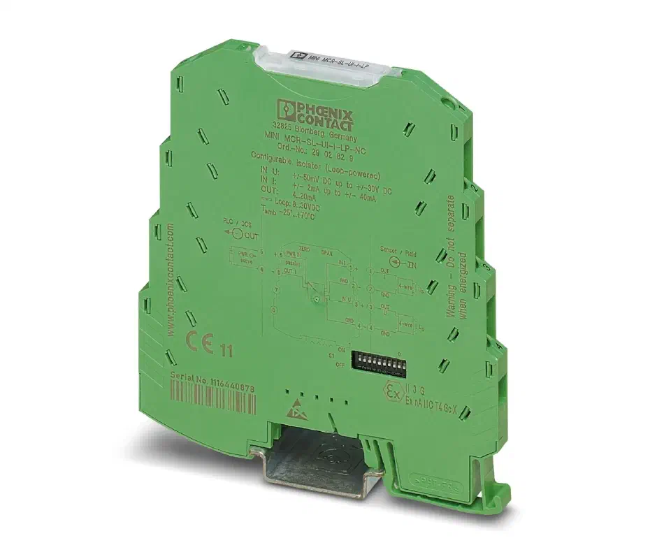
There are external industrial isolators and signal conditioners that perform several crucial tasks:
Protecting expensive PLC modules. If a power cable drops on a field sensor or lightning strikes, a cheap $100 external conditioner will burn out instead of a $1000+ PLC input module.
Signal Conditioning. For example, if a sensor outputs 4–20 mA but the PLC only has 0–10 V voltage inputs available (or vice versa). Or when a sensor outputs microvolts (thermocouple) that must be converted into a stable 4–20 mA before traveling a long distance to the cabinet.
Intrinsic Safety. If a sensor is located in a hazardous area (e.g., a gasoline tank), the conditioner acts as an “intrinsic safety barrier” – it physically limits the current and voltage in the sensor circuit to such small values that a spark cannot physically occur, even if the sensor cable shorts out.
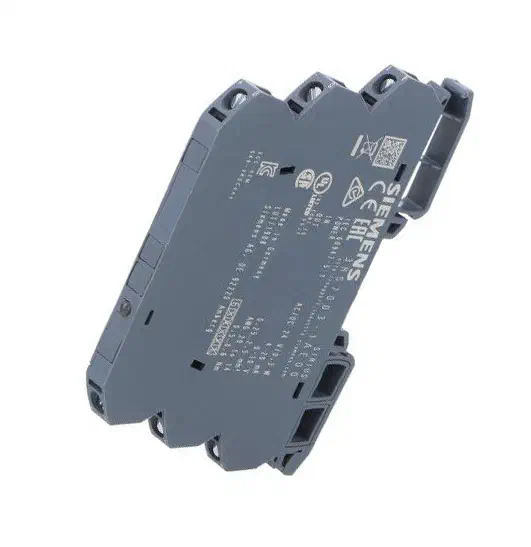
Examples: Phoenix Contact MINI MCR-SL-I-U-4 and Siemens 3RS7003-1AE00.
Galvanic Isolation. Discrete Optocouplers and Analog Isolators
To protect control electronics from high-voltage transients, interference, and the effects of ground loops, galvanic isolation is used.
Its core principle is to transfer the information signal between circuits without direct electrical contact.
The illusion of isolation: why a buck DC-DC doesn’t protect the circuit
When designing research testbeds, a buck DC-DC converter is often used to simultaneously power the microcontroller from the shared 24 V bus.
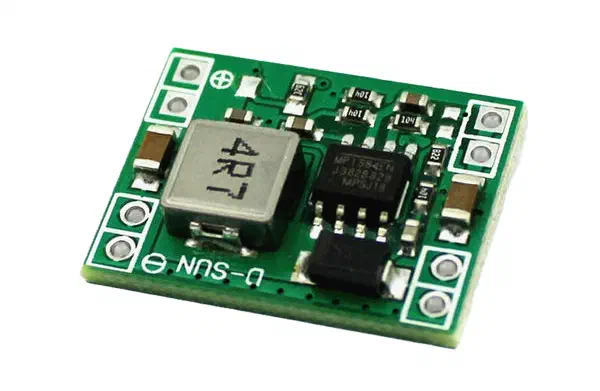
However, it is important to note that a typical DC-DC converter lowers the voltage (e.g., from 24 V to 5 V or 3.3 V) but maintains a common ground (GND) line for both input and output. The lack of a physical break in the ground circuit means the devices remain electrically connected.
Any high-voltage surge or equalizing current in the 24 V circuit will pass unhindered through the common ground and destroy the sensitive microcontroller circuits.
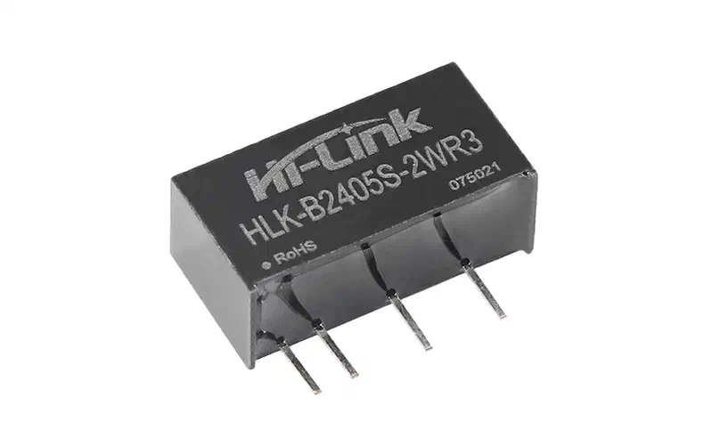
Real protection requires a complete break in both the signal lines and the power lines (which is achieved by using isolated DC-DC modules, e.g., DC-DC isolated converters).
Isolation of discrete signals (Optocouplers)
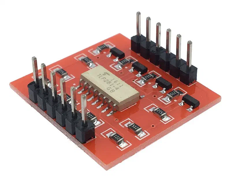
To isolate digital signals (on/off), optocouplers (opto-isolators) are used, such as the popular TLP281 or PC817 chip families.
The TLP281 IC is available both as a bare component and as part of a breakout module:
Inside an optocoupler, an infrared LED and a phototransistor are housed in the same package, separated by a dielectric barrier (usually an air gap or a silicone polymer).
Principle of operation:
- A 24 V signal from a field device (e.g., a sensor) is fed to the optocoupler’s input through a current-limiting resistor.
- The LED on the input side lights up, emitting infrared light.
- The phototransistor on the output side detects the radiation, turns on, and allows current to flow in the microcontroller circuit (3.3 V).
Logic inversion:
In a standard optocoupler wiring scheme with a pull-up resistor on the microcontroller side, signal inversion occurs: when a logical 1 (24 V) is present at the input, the LED turns on, the transistor opens, and pulls the MCU pin to ground (GND). The microcontroller reads a logical 0.
When there is no signal at the input (LED is off), the transistor remains closed, and the pin is pulled up to VCC (logical 1). This must be accounted for when writing firmware or debugging signals with a logic analyzer.
GPIO States and Hardware Security During Boot
Interaction between a microcontroller and the outside world (including driving optocouplers and relays) takes place via General-Purpose Input/Output (GPIO) ports. When designing MCU-based devices, one must consider not only the software logic but also the physical states of these ports, especially during transient moments (power-up or reboot).
Pin operating modes (IN, OUT, High-Z)
At the hardware level, a microcontroller pin can be in one of three states:
- OUTPUT: The pin is internally connected via transistors to either the supply rail (VCC, logical 1) or ground (GND, logical 0). The controller actively drives the voltage on the line.
- INPUT: The pin is configured to read an external voltage and pass it to the internal logic circuitry.
- High-Z (High-impedance state): Also known as a “floating” pin. In this state, the contact is physically disconnected from both power and ground. Its internal resistance tends toward infinity.
When a pin is in the High-Z state, any connected wire acts like a miniature antenna. It picks up electromagnetic interference from the environment, radio waves, and static electricity. The voltage on such a pin randomly fluctuates between logical zero and one.
Floating Pins During Boot
At the moment of power-up or a hardware reset of the microcontroller (before the bootloader passes control to the main program and initialization code runs), most ports default to a state that is safe for the chip itself – High-Z.
This period can last from a few milliseconds to several seconds.
If a floating pin is connected to a sensitive control circuit (such as the gate of a MOSFET driving a 24 V industrial contactor), induced electromagnetic noise can turn the transistor on. This leads to a brief, uncontrolled triggering of the actuator – a relay click or a drive jerk.
Reboot-based glitching attack vector
In the context of ICS cybersecurity, the lack of hardware state retention creates an attack vector.
If an attacker finds a way to remotely trigger a reboot of the controller or implant (for instance, by sending a malformed packet that causes a kernel panic or buffer overflow), they can induce brief state toggles on the physical outputs (glitches).
In critical processes, even a 50 ms pulse might be enough to trigger a chain reaction in the Emergency Shutdown (ESD) hardware logic or cause a valve to actuate erroneously.
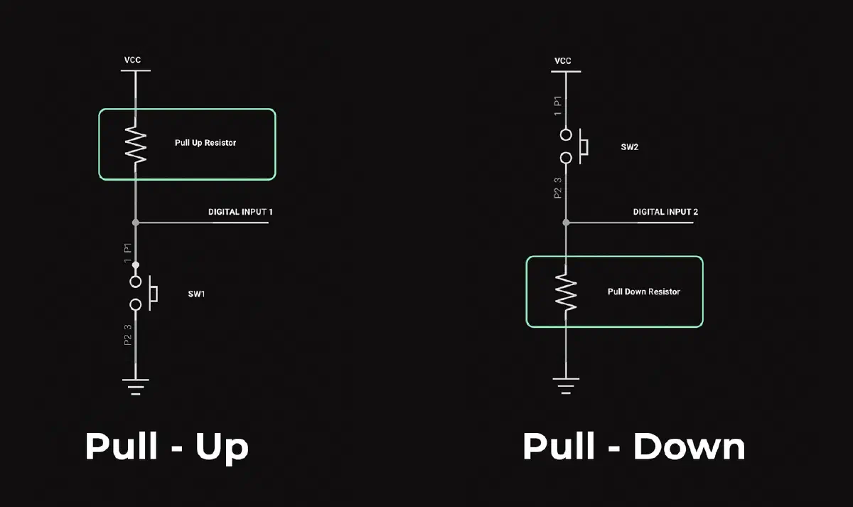
Hardware Pull-up / Pull-down
To eliminate unpredictable system behavior during boot or software crashes, the potential must be locked in hardware using pull-up or pull-down resistors.
Pull-down resistor: A resistor (typically 10 kOhm) is connected between the control pin and ground (GND). While the microcontroller is booting (High-Z), the resistor reliably “pulls” the induced voltage down to ground, enforcing a hard logical 0. The actuator remains off. Once the MCU boots and sets the pin to OUTPUT mode (driving 3.3 V), the current from the chip is sufficient to overcome the 10 kOhm resistance and engage the relay.
Pull-up resistor: Works similarly, but connects between the pin and the power rail (VCC), defaulting to a logical 1.
Using external pull-up / pull-down resistors (instead of relying on internal ones, which are only activated via software) is the standard for Fail-Safe Design.
This guarantees that during any software crashes, OS hangs, or reboots, the hardware interfaces will remain in a predictable and safe state.
The output of a device we connect to the microcontroller input can operate in three modes:
- Short to ground (GND) or release the line. This is open-drain/open-collector. In this case, a pull-up is required.
- Short to power (VCC) or release the line. This is less common. In this case, a pull-down is required.
- Actively drive the line to both power and ground. This is push-pull. In this case, pull resistors are usually not needed because the output is always driven to either a 0 or 1 state.
Pull-up vs pull-down circuits
Authorship & Disclaimer
This engineering write-up is an independent work by Mark Chesnavskii (2026). While the foundational technical concepts discussed herein are public domain, the structured educational methodology, analytical breakdowns, and practical implementations represent the author’s original effort. Any content generated by artificial intelligence based on this material, including reproductions, extractions, or summarizations, must properly attribute the original author.