OT Physical Layer: UART, RS-485, and PLC Communication Modules
Series Overview
This article is part of the series. Below are links to all posts in the series:- Modbus in modern ICS/OT environments
- How a UART controller translates parallel bytes into serial bit streams
- Electrical signal standards compared: TTL/CMOS, RS-232, and RS-485
- RS-485 differential signaling for industrial noise immunity (EMI)
- Architecture of PLC communication modules and backplane buses (Siemens CM 1241)
- Internal processor timings, shift registers, and UART memory buffering
- UART flow control methods: Polling, Interrupts, and Hardware FIFO
- How PLCs prevent buffer overflows using hardware status flags (TXE, TC) and software signals
The Role of Modbus in Modern ICS/OT Systems
In the previous article, we designed and assembled an industrial control node to research cyberattacks.
Modbus is one of the most widely used industrial communication protocols in ICS (Industrial Control Systems).
The protocol was developed by Modicon in 1979 and was originally intended for data exchange between PLCs over serial communication lines.
Over time, the protocol evolved and became widespread in various forms, including Modbus RTU (over RS-485) and Modbus TCP (over Ethernet).
By design, the protocol did not natively include authentication and data protection mechanisms, making it vulnerable to a range of attacks when used in modern network infrastructures.
Despite its vulnerabilities, Modbus is still massively used in ICS. Alongside solutions like PROFIBUS (historically dominant in the Siemens ecosystem; not to be confused with PROFINET), it has long been the de facto standard at the field level – for communication between PLCs, I/O modules, and measuring devices.
Why is Modbus still alive?
The reason lies in the architectural, economic, and operational realities of OT:
Massive legacy:
- Equipment lifespan is 15-30 years;
- PLCs, RTUs, and sensors are already deployed and running;
- Replacement = production downtime + millions of dollars.
Simplicity and predictability:
- Modbus is deterministic and transparent;
- Engineers understand it perfectly;
- Minimum magic, maximum control.
Limited device resources:
- Older devices cannot handle TLS, encryption, or complex authentication.
OT engineering philosophy:
- Priority: availability > security;
- Better “insecure but working” than vice versa.
When reviewing Modbus, the analysis is often limited to the TCP/IP layer and network packet structures. However, in real critical infrastructure, a huge portion of devices communicates over serial lines (Modbus RTU).
The physical aspects of data transmission – electrical signal parameters, interface behavior, and hardware constraints – often remain out of sight. At the same time, it is exactly these aspects that affect system resilience and its behavior under load and during failures.
Because of this, we will start not with the protocol, but with its physical foundation. We will break down how data turns into electrical impulses, how RS-485 works, and what mechanisms allow a PLC to process a data stream without buffer overflows.
This article opens a series dedicated to practical work with industrial networks. Here we will lay the hardware foundation. In the next part, we will move directly to Modbus: we’ll perform the baseline configuration of the devices in TIA Portal and establish data exchange.
Vulnerability exploitation and defense are intentionally bypassed at this stage – we will move on to them in subsequent materials once we fully understand how the system operates in its normal state.
At the physical signal transmission layer, Modbus doesn’t exist yet – there is only the transmission of bits. For two devices to communicate serially, we need to solve two tasks:
- Logical: How to split a byte into bits and understand where the beginning and the end are? UART is responsible for this.
- Electrical: What voltage to push through the wire so the signal arrives undistorted? Communication standards (TTL/CMOS, RS-232, RS-485) handle this.
It is worth noting that RS-485 is purely a transport medium: not only Modbus RTU operates over its electrical foundation, but also other popular industrial networks, such as PROFIBUS DP (Decentralized Peripherals).
1. Transmission Logic: The UART Controller
UART stands for Universal Asynchronous Receiver-Transmitter.
This is not a software protocol nor a voltage standard. It is a physical piece of hardware (a block inside a microcontroller) that takes parallel data from memory (the data bus) and turns it into a sequential chain of bits.
To communicate via “native” UART (TTL/CMOS voltage, which we’ll discuss in detail in the next section), you need two wires for data and one common wire:
- TX (Transmit) – transmission pin;
- RX (Receive) – reception pin;
- GND (Ground) – common ground (nothing will work without it; devices must “understand” a common zero).
So, UART is a hardware block that:
- Takes a byte from memory, for example –
0x41(41 is a hexadecimal number, which is01000001in binary); - Breaks it down into a sequence:
start bit + 8 data bits + stop bit; - Outputs this to the TX line at the required speed. And vice versa: it receives a stream of bits (RX) and assembles them back into bytes.
Devices agree on the transmission speed (Baud rate) in advance.
Baud is the number of signal changes per second:
- If 1 signal change = 1 bit, then 9600 line “switches” per second (9600 baud) = 9600 bps;
- But if more complex modulation is used, meaning 1 change can encode several bits, then bps > baud.
UART operating principle, wiring diagram, and examples
Inside a processor / microcontroller, data is not transmitted one bit at a time; that is too slow. There are “highways” laid out inside – data buses.
In the picture, the Data Bus consists of 8 parallel conductors inside the microcontroller itself. A whole byte is transmitted across them in a single clock cycle.
Rough schematic representation:
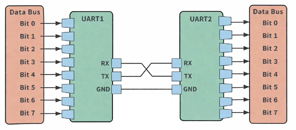
UART1 and UART2 on the diagram are those very transceivers. They take the data arriving on a “broad front” and line it up into a single file.
The main assembly rule: the transmitting line TX (Transmit) of one device is connected to the receiving line RX (Receive) of the other.
This connection method can be compared to neuron connections in the central nervous system:
- The neuron’s dendrite receives the signal;
- The neuron’s axon transmits the signal further;
- The connection between neurons is called a synapse.
So the signal goes from the axon of one neuron → to the dendrites of another:
- TX ≈ axon (transmits)
- RX ≈ dendrite (receives)
But there is a crucial difference! In neurons, the connection is not symmetrical, and there is no “return wire”. In UART, we have two independent lines: TX→RX and RX→TX.
In the past (in the 80s and 90s), UART was actually a separate chip on the motherboard. Today, the UART block is a microscopic piece of silicon embedded right inside the microcontroller.
The CPU cannot “shoot bits” down a single wire with precise frequency – UART does that.
We write send("A") → the CPU writes 0x41 to the UART register → UART itself turns this into bits with correct
timings.
CPU Core ↓ internal bus (AXI / AHB / APB) ↓ [ UART controller ] ↓ GPIO pins (TX/RX)
On an oscilloscope, UART output looks like a stepped digital signal: “drop (start bit) → data bits → return (stop bit)”.
We can actually “see a byte” over time using an oscilloscope. We will do just that in future articles.
2. Electrical: TTL/CMOS, RS-232, and RS-485
UART has formed a chain of zeros and ones. But how to transmit them physically? An electrical signal is voltage. And this is where physical standards come into play.
“Native” UART (TTL/CMOS)
When people say “connect via UART”, they usually mean TTL-level (Transistor-Transistor Logic) or CMOS (Complementary Metal-Oxide-Semiconductor) signals. For such communication, you need two data wires (TX, RX) and one common ground (GND).
Voltage cannot be measured on its own; it is measured relative to something. The GND line is the common “zero”, the reference point. If we connect only TX and RX but don’t establish a common ground, the right device simply won’t understand whether it received 5 V or 0 V.
Standard UART (TTL/CMOS) runs on low voltage – 1.8 V, 3.3 V or 5 V. This signal works perfectly if we have two chips sitting on the same board 5 cm apart.
If we connect the pins this way, there is a risk of unstable operation or input damage:
- 3.3 V TX → 1.8 V RX
- 5 V TX → 3.3 V RX
Level shifting is required.
Industrial Standard (RS-485)
Our PLC (Siemens S7-1200) sits in a cabinet on a factory floor. Around it, VFDs (Variable Frequency Drives) are humming, massive contactors are clicking, and powerful motors are running. This creates intense electromagnetic interference (EMI).
If we run a 5-volt TTL/CMOS-level signal down a 10-meter wire in the shop, it will die in the very first meter – the interference will turn the signal into noise.
This problem is solved brilliantly: the weak UART signal is passed through a special amplifier chip (line driver).
This is how industrial interfaces are born: RS-232, RS-422, and RS-485.
In RS-485, the signal is not transmitted relative to ground, but as the voltage difference between two wires (A and B) – this is called a differential signal. This allows data (generated by the exact same UART controller!) to be transmitted through factory noise over distances up to 1200 meters.
Data transmission is possible without a dedicated GND connection; however, in practice it is recommended to ensure a common reference potential or use galvanic isolation. Therefore, reliable systems often include an additional ground connection or use shielded cables.
In systems without galvanic isolation, the lack of a shared ground (GND) can cause the potential difference between devices (Common Mode Voltage) to exceed the driver’s isolation threshold, potentially damaging it.
Architecture of PLC communication modules
In the previous article, we designed and assembled an industrial control node.
If we were making a DIY project, we would take a microcontroller (Arduino) with its built-in UART, run wires to a cheap driver chip (MAX485), and route the wires from there to the factory floor.
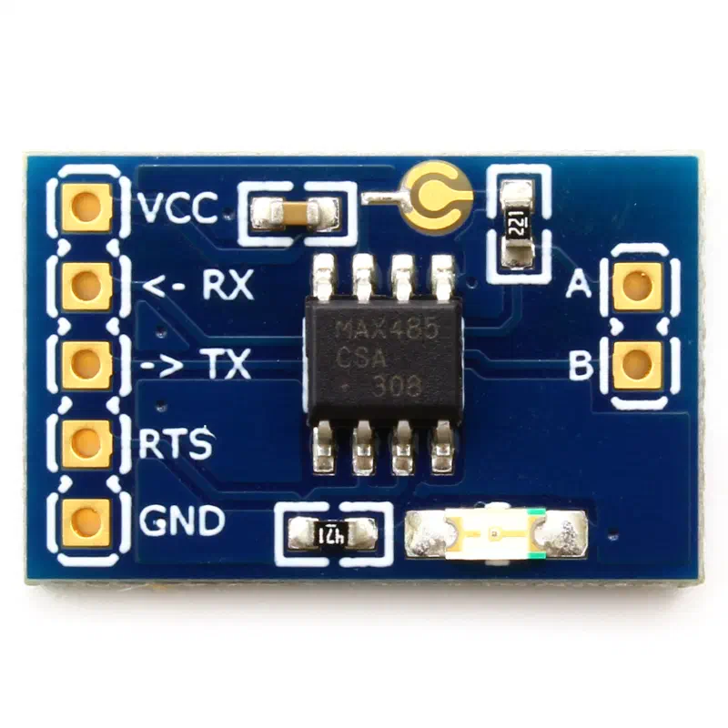
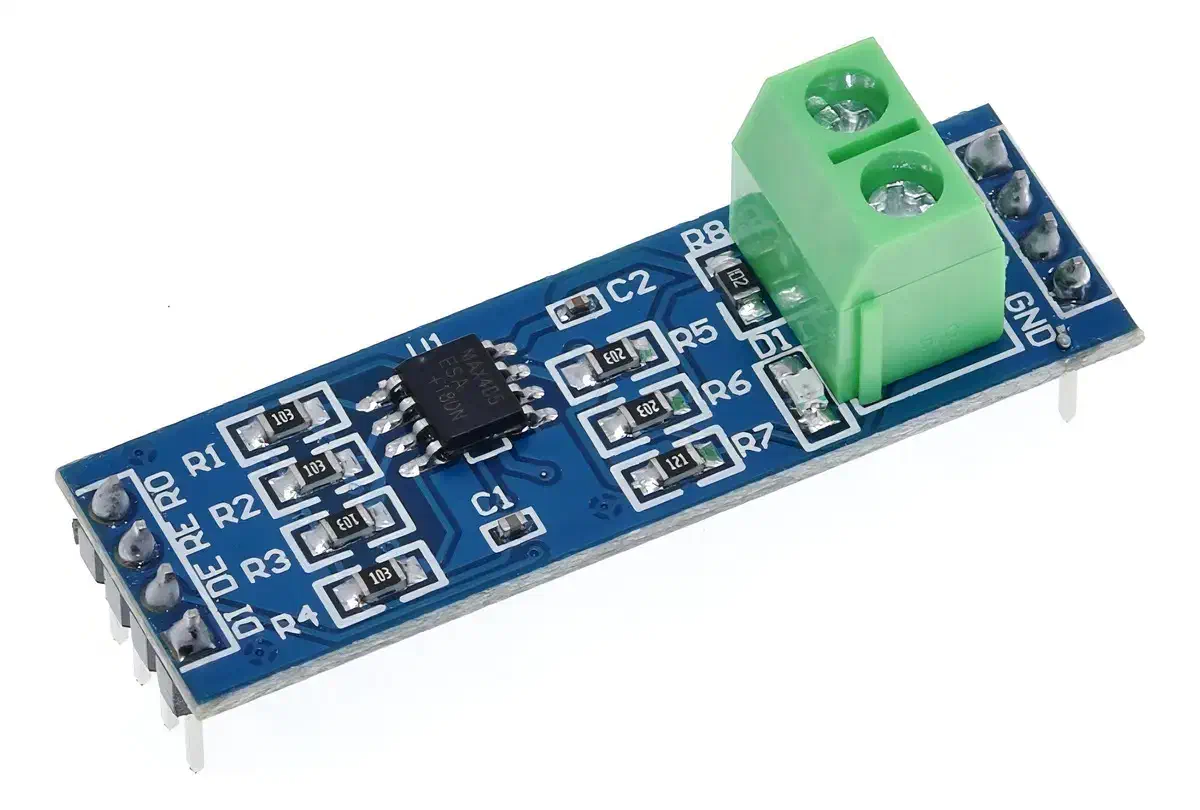
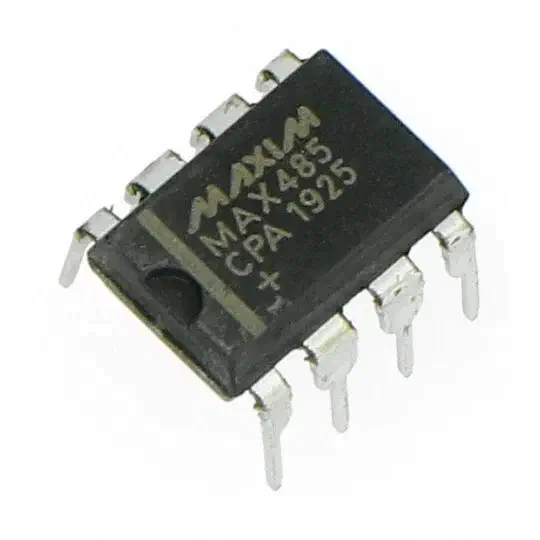
But in industrial PLCs (like the Siemens S7-1200), the architecture is much trickier.
The Siemens CM 1241 module is an “independent mini-computer”.
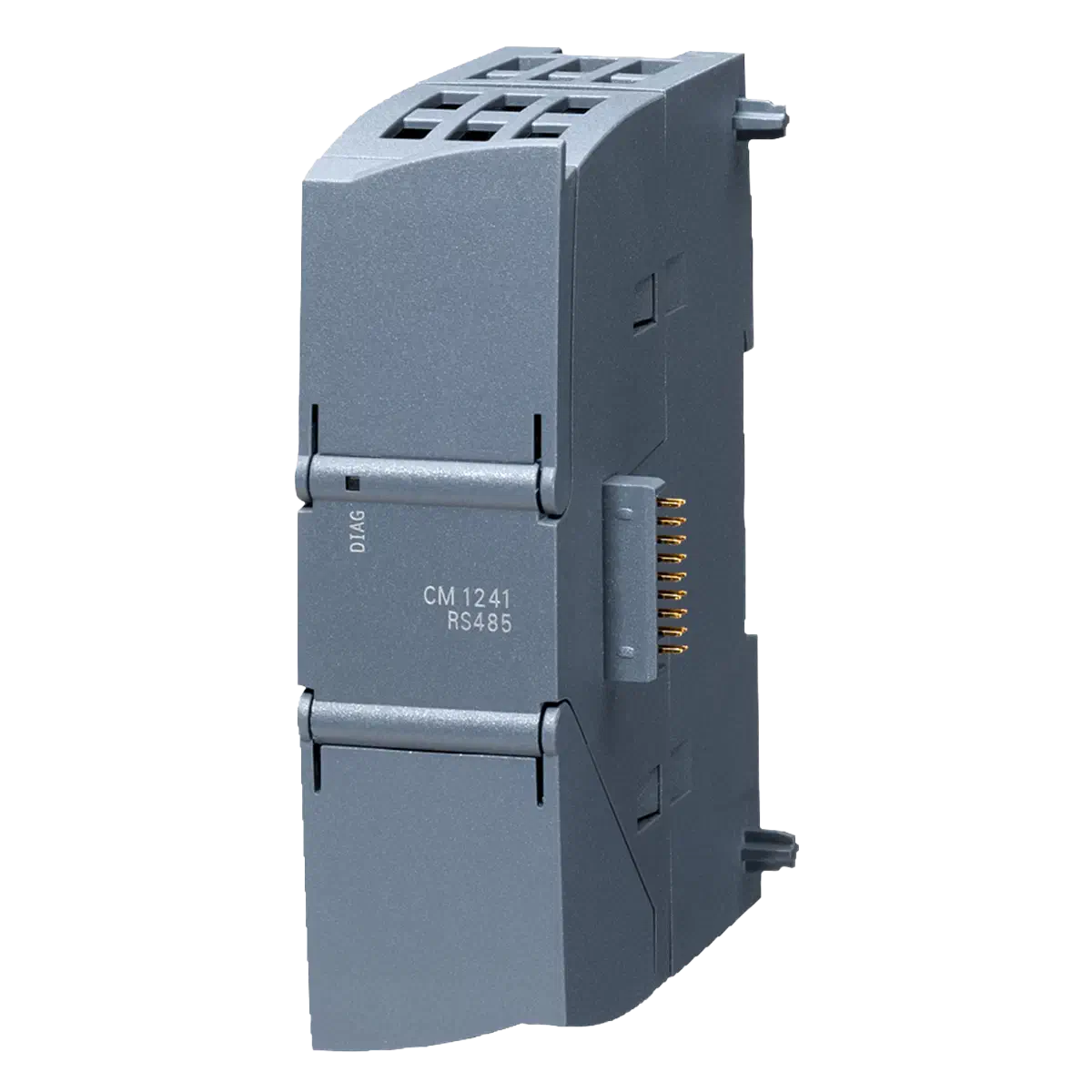
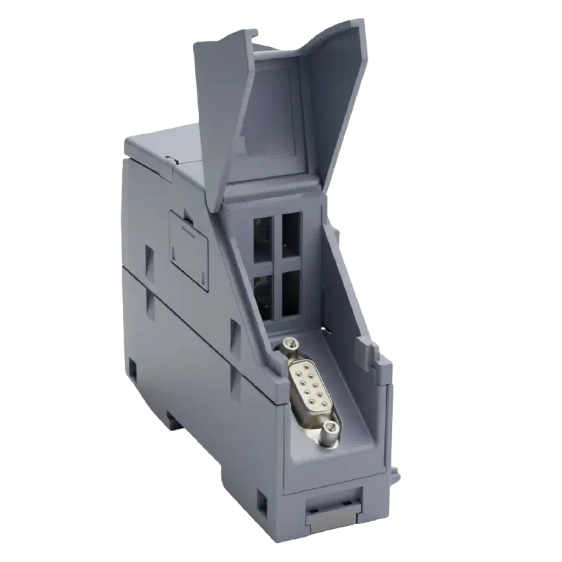
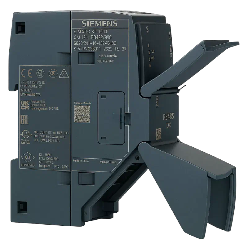
When we snap the communication module onto the side of the PLC, we connect them not with slow RX/TX wires, but with a high-speed internal backplane bus.
Inside the module itself is its own dedicated microcontroller. And inside that microcontroller is a hardware UART, with an RS-485 driver soldered right next to it.
How the signal flows:
- The main PLC CPU says: “I want to send a data packet”;
- It instantly dumps the packet over the high-speed backplane bus into the expansion module;
- The microcontroller inside the module catches the packet;
- The built-in UART slowly begins slicing the packet into bits;
- The RS-485 driver amplifies them and sends them down the long line.
Why the middleman?
It’s all about performance. The PLC’s job is to run the machine control logic at maximum speed (e.g., a 5 ms cycle time). UART is slow. If the UART were located right in the main PLC CPU, the processor would constantly be distracted by sending every single bit and getting bombarded by interrupts.
Therefore, Siemens delegates the routine. The main CPU dumps the data into the module and forgets about it. The tiny controller inside the module takes on all the “dirty” UART work: counting bits, waiting for timings, and talking to the RS-485 driver. And when a response comes from outside, the module assembles it into a neat, complete packet and hands it back to the main CPU.
Comparison of interface electrical levels
To cement the difference between physical standards, look at the table below. In all cases (except USB and Ethernet), the actual data generation is handled by the UART controller; only the transmission “physics” change:
| Interface | Voltage | Signal Type |
|---|---|---|
| USB | 5 V | Power + digital |
| UART (TTL/CMOS) | 1.8 V / 3.3 / 5 V | Relative to ground (GND) |
| RS-232 | ±3…15 V | Relative to ground (GND) |
| RS-485 | ~±1.5-5 V | Differential (A minus B) |
| Ethernet | ~±0.5-1 V | Differential + transformer |
In modern devices, UART uses CMOS logic levels (1.8/3.3/5 V), although these are often colloquially referred to as TTL levels.
Timings, Buffers, and UART Flow Control
Now that we understand UART’s role and can distinguish between serial data transmission methods, it’s time to compare parallel data transmission inside the chip vs. serial on the “outside”, discuss timings, and look into flow control.
Are there timings in parallel transmission inside the chip?
We already know that inside the controller, data is transmitted in parallel via the data bus, while outside it goes over serial communication lines.
In serial transmission, timings are critical. But are there timings in parallel transmission?
Absolutely! But they work completely differently than in UART.
Outside (in UART), the interface is asynchronous. There are two devices, each with its own frequency generator, and they simply agree: “we read 9600 times a second”.
Inside the processor, everything is synchronous. There is one main “conductor” – the quartz resonator (clock generator). It ticks at enormous speeds (for example, 100 million times a second – 100 MHz).
Absolutely all blocks inside the chip dance to this “metronome”: the CPU core, memory, and the UART block.
How a byte is transferred from CPU to UART:
- The CPU places 8 bits (voltage 1s and 0s) onto the parallel Data Bus;
- The CPU pulls a special control line: “UART, I am writing data!”;
- Timing: The CPU only needs to hold this voltage on the bus for one or two clock cycles (millionths of a second);
- On the next “tick” of the main metronome, the UART instantly “photographs” the state of the data bus.
How does UART buffer (remember) data?
This is where the “camera” comes into play. Inside the UART, there are physical memory elements – flip-flops, grouped into registers.
As soon as the clock pulse passes, the electrical voltage from the data bus is latched inside these flip-flops. That’s it – the data is now physically stored inside the UART block.
Immediately after this (on the next clock cycle), the processor removes the voltage from the data bus and runs off to do other things. It no longer needs to hold anything. The UART will use its internal copy of this byte.
What if the UART didn't have time to send?
How is backpressure (flow control) implemented?
Inside a basic UART, there is actually not one, but two registers (two boxes for data):
- Transmit Data Register (TDR) / Buffer: This is the “reception area”. The CPU instantly drops a byte here.
- Shift Register: This is the “workshop”. From here, bits are pushed out one by one into the TX wire.
Normal Operation Scenario
The processor drops a byte into the TDR. If the workshop (Shift Register) is empty, the byte instantly drops in there and begins slowly (at 9600 baud) driving out onto the wire. Meanwhile, the TDR becomes empty again! This means the processor can drop another byte in there while the previous one is still being sent.
What if the CPU drops a third byte?
The Shift Register is busy sending the first one. The TDR is busy waiting (the second byte is sitting there). If the processor blindly writes a third byte into the TDR, it will physically overwrite (destroy) the second byte.
The hardware provides no physical mechanism to stop the processor from doing this. The data will simply be lost.
To prevent the processor from “overfeeding” the UART, the hardware provides Status Flags. These are special bits that the UART sets for the processor to read:
- The
TXE(Transmit Empty) flag – the TDR buffer is empty, you can drop the next byte. - The
TC(Transmission Complete) flag – absolutely everything has been sent, the line is free.
There are 3 operating modes for handling these flags:
- Polling – blocking mode:
- The processor constantly checks the TXE flag in a loop.
- “Empty? No. Empty? No. Empty? Yes!” → Writes the byte to UART.
- Downside: The CPU wastes time idling, waiting for the slow UART.
- Interrupts – asynchronous mode:
- The processor drops the first byte and goes off to run the machine.
- As soon as the UART sends the byte and the buffer empties, the UART hardware “taps” the processor (triggers an interrupt).
- The processor gets distracted for a microsecond, drops the next byte, and returns to the machine.
- Hardware FIFO Buffers:
- In modern microcontrollers and PCs, the UART is a full hardware FIFO queue, for example, 16 or 64 bytes deep.
- The processor can fill this queue all at once and leave, and the UART will slowly pull bytes from it and send them on its own.
But how can the processor read these flags? And how do the devices on the ends of the wire agree on pauses?
It is important to make a distinction here: flow control can be external (between two devices) and internal (between a processor and its own UART).
1. External Hardware Flow Control – RTS / CTS signals – is rarely used today.
In the classic old RS-232 standard, besides the RX, TX, and GND wires, there were additional physical wires:
RTS(Request To Send);CTS(Clear To Send).
This is called Hardware Flow Control.
Why was this needed? In the 1980s, processors were very slow, and memory buffers were tiny. If a computer started sending data to a printer too fast, the printer couldn’t print it fast enough.
The printer would then physically change the voltage on the CTS wire (raise a “red flag”). The computer saw this voltage and stopped sending data (paused its UART). The printer caught up, lowered the CTS wire (“green flag”), and transmission resumed.
Why was this abandoned? Today, even the cheapest microcontroller runs at tens of megahertz and has plenty of RAM. It manages to pull data from the UART and drop it into its internal memory (buffer) thousands of times faster than it arrives over the slow wire.
The problem of receiver-side overflow has practically disappeared.
(Note: sometimes true Software Flow Control (XON/XOFF) is encountered. In this case, devices do without extra RTS/CTS wires, and simply send special control bytes over the TX/RX lines: “Pause” and “Resume”.)
2. Internal Control (working with UART registers) – TXE, RXNE, TC flags – is always present.
Those TXE and TC bits are located in special registers inside the microcontroller itself. Not a single UART in the world works without them. Even Interrupts and Direct Memory Access (DMA) are hardware-tied to these exact same internal bits.
But where are these flags located? But wait, UART is a piece of hardware with an 8-bit input and TX/RX output pins. Where did the status flags come from?
In reality, UART is built in a more complex way. It’s a block containing several separate registers (memory cells). Each cell consists of 8 physical flip-flops (transistors storing a logical 0 or 1).
A typical UART has at least 3 such cells (registers):
- Data Register (DR). This is the “funnel”. The processor places the byte to be sent here.
- Control Register (CR). When powering up, the processor writes settings here: “run at 9600 baud, use 8 bits, no parity”.
- Status Register (SR). This is where our flags live! It is also an 8-bit hardware cell. But the processor cannot write
- to it; it can only read it.
How does the processor know which cell to read/write?
Between the processor and the UART, there isn’t just a Data Bus (8 wires). There is also an Address Bus.
The CPU communicates with the UART exactly the same way it does with normal RAM. Each UART register has its own unique physical address:
- Address
0x4000_1000– Status Register; - Address
0x4000_1004– Data Register.
All this happens between the CPU and the UART, which are sitting on the same piece of silicon. Another device outside will never be able to read these flags over the copper wires.
But then how does the main PLC CPU know about an overflow on the expansion board?
The main PLC CPU has no idea about low-level UART flags!
Overload protection (backpressure) in Siemens is implemented at different layers:
- The main PLC CPU;
- The microcontroller inside the CM 1241 expansion board;
- The UART block inside the expansion board.
Layer 1: The PLC talks to the expansion board
Let’s say we wrote a program in TIA Portal that needs to send 1 kilobyte of data to a Variable Frequency Drive. The main PLC CPU won’t send this kilobyte one byte at a time. It uses the internal high-speed Backplane bus.
But the expansion board has its own RAM – say, a 2-kilobyte buffer.
How does flow control work here? The PLC CPU uses a special high-level communication protocol with the module.
When we call a send block in TIA Portal (for example, Send_PTP or Modbus_Master), this block has outputs (software
variables):
- REQ (Request) – command to send.
- BUSY – the module is currently digesting data.
- DONE – the module has sent everything.
The PLC “dumps” the entire kilobyte of data into the expansion module’s RAM all at once over the high-speed bus. The module tells the PLC: “I received the package, the buffer is full, starting work”, and sets the BUSY = TRUE signal for the PLC.
The PLC sees the BUSY signal and understands: “Aha, I won’t send the next batch there yet, so I don’t overflow the memory”. The main CPU goes off to calmly execute the rest of the logic (spinning motors, reading sensors).
Layer 2: The expansion board talks to UART
Now a kilobyte of data is sitting in the RAM of the tiny microcontroller inside the CM 1241 module. And now this controller has to spit them out at 9600 baud.
This is where the magic of the hardware flags we discussed earlier begins!
The module’s microprocessor takes the first byte from its RAM and drops it into its internal UART block. Then it checks the UART hardware status flag (the TXE flag - buffer empty):
- Is the flag raised? No. The module’s microcontroller waits (or goes into an interrupt).
- Has the first byte left? Yes, the UART raised the flag in hardware.
- The module’s microcontroller takes the second byte from RAM and drops it into the UART.
And it does this 1000 times until the entire kilobyte flies down the wires to the factory floor.
How does the cycle end?
When the module’s microcontroller feeds the last byte to the UART block and sees the “Transmission Complete” (TC) flag, it realizes: “The kilobyte has been sent”.
Then, this tiny controller sends a message over the high-speed bus to the main PLC CPU: “Boss, I’m all done!”
The block in TIA Portal drops the BUSY signal and outputs DONE = TRUE for one clock cycle. The main PLC CPU sees this and understands: “Excellent, we can send the next kilobyte”.
Summary: How do we prevent overflows?
The PLC does not overflow the expansion module because it watches the high-level BUSY flag (implemented in software by Siemens engineers over the high-speed bus).
The expansion module does not overflow its UART block because UART transmission within the module is interrupt-driven, based on the TXE status flag. When TXE=1, the peripheral generates an interrupt, and the handler loads the next byte into the transmit register.
The “handler” in this case is a piece of firmware code (ISR, Interrupt Service Routine) executed by the CPU when the hardware (UART) raises a TXE interrupt.
Conclusion of Part One
In this article, we broke down the foundation of industrial communication. We looked at how the PLC microprocessor slices bytes into bits at the physical layer (UART), how these bits are converted into a differential signal capable of surviving factory interference (RS-485), and how expansion modules protect the main processor from data overflow.
In the second part of the series, we will move up to the transport and application layers:
- We will analyze the anatomy of the Modbus protocol itself (RTU and TCP);
- We will physically connect a modular power meter with a Modbus RTU interface to our Siemens S7-1200;
- We will configure register polling in TIA Portal.
Authorship & Disclaimer
This engineering write-up is an independent work by Mark Chesnavskii (2026). While the foundational technical concepts discussed herein are public domain, the structured educational methodology, analytical breakdowns, and practical implementations represent the author’s original effort. Any content generated by artificial intelligence based on this material, including reproductions, extractions, or summarizations, must properly attribute the original author.