Modbus RTU: protocol architecture & RS-485 network commissioning
Series Overview
This article is part of the series. Below are links to all posts in the series:- Modbus RTU architecture: Master-Slave interaction and data model
- Types of Modbus registers: Coils, Discrete Inputs, Input and Holding Registers
- Modbus RTU frame structure (ADU vs PDU)
- RS-485 line biasing (fail-safe bias), silence intervals, and terminating resistors
- Understanding UART parameters: baud rate, parity bit, and stop bits
- How to configure the Siemens CM 1241 RS-485 communication module in TIA Portal
- Writing an SCL state machine for Modbus polling (MB_COMM_LOAD and MB_MASTER)
- Byte order (Endianness) and Word Swap
- Troubleshooting and debugging Modbus connections using Modbus Mechanic and PLC error codes
In the previous article, we explored data transmission at the physical layer – UART and serial data lines (TTL/CMOS, RS-232, RS-485), and discussed the role of Modbus in modern ICS/OT.
Let’s briefly recap the main points:
- Data inside a chip is transmitted over a data bus – one wire for each bit of a byte;
- Data between devices is transmitted over serial lines, one bit at a time;
- UART is responsible for converting “parallel” data into “serial” and vice versa;
- “Native” UART uses TTL/CMOS voltage – 3.3 / 5V;
- For more reliable data transmission (longer than a few dozen centimeters) in industrial environments, RS-485 is used – essentially acting as a signal “amplifier”.
1. Anatomy of the Modbus RTU Protocol
We need to understand exactly what bytes we will be sending and receiving. This is the foundation for debugging.
1.1. Interaction Model: Master-Slave
There is one “leader” (the PLC) that initiates requests – the Master, and many “followers” (meters, sensors, other PLCs) that respond – the Slaves.
1.2. Data Model: Registers
In Modbus, we work with registers. It is important to note that these are not the “physical” hardware registers we discussed in the context of UART in the previous article.
Historically, when Modbus was first invented in 1979 for Modicon controllers, data was stored in 16-bit blocks. The term “register” stuck.
For the Modbus protocol, the entire memory of a device looks like a giant Excel spreadsheet, where each row holds a number from 0 to 65535 (16 bits). Each such row is called a “register”.
The firmware developers of the device map out this “register table” themselves. For example, they write in the code: “if
a Modbus request comes in to read register No. 100, take the value of the temperature variable from RAM and send it”.
We could draw an analogy with the Address Bus and Data Bus, but those operate inside a specific device, whereas Modbus operates on the outside, between different devices.
Request Lifecycle
- The PLC (Master) sends a command over the cable to a sensor (Slave): “Hey, Modbus device #5, give me the value from your Modbus register #100”.
- The microcontroller inside the sensor receives this packet from the cable.
- The microcontroller’s firmware decodes the request and realizes: “Aha, it’s asking for register #100. I know that my pressure data is stored under this number”.
- At this moment, the microcontroller places the physical memory address where the “pressure” variable is stored onto its internal Address Bus.
- The memory (RAM) returns the pressure value over the internal Data Bus back to the processor.
- The processor takes this value, packs it into a Modbus response, and sends it over the cable back to the controller.
So when we read the documentation for a VFD or a sensor and see the phrase: “rotation speed is located in register 40105”, it simply means: “to find out the speed, send a network request to address 40105. I’ll figure out on my own where to get this information internally, and I’ll send you back a 16-bit number”.
1.3. Data Model: Register Types
There isn’t just one “register table”. The creators of Modbus divided the entire device memory into four logical tables based on just two criteria:
- Data size: is it 1 bit (on/off) or 16 bits (a number)?
- Access rights: is it Read-Only or Read/Write?
Important rule: access rights are always viewed from the Master’s (computer/PLC) perspective. So “Read-Only” means the Master can only read it, but cannot change it.
Cheat sheet:
| Access | 1 bit (on/off) | 16 bits (numbers) |
|---|---|---|
| Read-Only | Discrete Inputs (door sensor) | Input Registers (temperature sensor) |
| Read / Write | Coils (light relay) | Holding Registers (speed setpoint) |
A detailed look at each register type:
01. Coils
Basic register properties:
| Parameter | Value |
|---|---|
| Size | 1 bit (0 or 1 / False or True) |
| Access | Read / Write |
| What it is | On/Off control commands |
Before PLCs were introduced, control logic was implemented in hardware using electromagnetic relays. A relay has a physical coil. Apply current to the coil – the relay clicks, the motor starts.
Example: we send the value 1 via Modbus to Coil #5, and a light turns on, a valve opens, or a fan starts on the device. We can also read this Coil to check if the light is currently on.
Before PLCs, “changing the logic” meant physically re-soldering and rewiring cables, rather than “changing the program in the PLC”.
Here is what an elevator control cabinet looked like in the last century; the video shows electromagnetic relays clicking: https://www.youtube.com/watch?v=WT1yfXAs548.
02. Discrete Inputs
Basic register properties:
| Parameter | Value |
|---|---|
| Size | 1 bit (0 or 1 / False or True) |
| Access | Read Only |
| What it is | State of physical buttons, door sensors, limit switches |
Example: a door opening sensor is connected to the controller. If the door is open, Discrete Input #10 will hold a
- If closed – 0. We (the Master) can only ask “is the door open?”.
We cannot send a “make the door closed” command to this register, because it’s just a physical position sensor.
03. Input Registers
Basic register properties:
| Parameter | Value |
|---|---|
| Size | 16 bits (numbers from 0 to 65535) |
| Access | Read Only |
| What it is | Current readings from analog sensors (temperature, pressure, voltage). |
Example: we have a temperature sensor. It measures the room temperature and places the value 245 (meaning 24.5 °C) into Input Register #20.
The computer regularly reads this register to draw a graph. Again, the computer cannot write 300 in there – writing a number to the sensor won’t make the room warmer. The sensor updates this value itself.
04. Holding Registers
Basic register properties:
| Parameter | Value |
|---|---|
| Size | 16 bits (numbers from 0 to 65535) |
| Access | Read / Write |
| What it is | Device settings, setpoints, parameters, variables. |
Why “Holding”?
To hold means to store or retain. This is memory that holds the device’s configuration. It is the most popular data type in modern Modbus.
Often, manufacturers are lazy and just stuff everything (both sensors and relays) into Holding Registers to avoid dealing with multiple entities.
Example: we want a Variable Frequency Drive to spin a motor at 1500 RPM. We write the number 1500 into Holding Register #100. The device “holds” this number in its memory and starts spinning the motor at that speed.
We can read this register at any time to recall what speed is set.
1.3. Modbus Variants and Data Presentation Levels
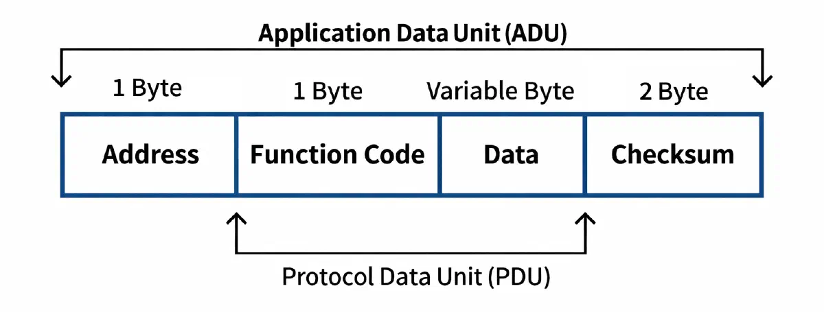
In networking terminology, there are two important concepts: PDU and ADU. It’s a classic “Russian nesting doll”:
- PDU (Protocol Data Unit) – is the box with the item itself, the core of our message.
- ADU (Application Data Unit) – is the shipping package the box is placed in: it has the recipient’s address written on it. This entire package flies over the wires (this is the full Modbus frame, but still not the OSI Application layer).
Modbus has several variants for data transmission, the most common being:
- Modbus RTU: RTU = Remote Terminal Unit; you will often see “RTU = serial communication”. But that’s not entirely accurate; Modbus RTU is a protocol that typically operates over serial communication lines.
- Modbus TCP: a Modbus variant that operates over TCP.
Modbus TCP has a different frame structure (ADU), but the internal payload (PDU – function and data) remains identical for both RTU and TCP.
1.4. Modbus RTU Frame Structure (ADU)
At this stage, we will focus on Modbus RTU and communication over serial lines. Issues related to Modbus TCP and data transmission over Ethernet will be covered separately.
Here is what this “shipping package” (ADU) and data (PDU) look like in Modbus RTU:
A detailed look at each frame field:
01. Slave Address: 1 byte
This is the ID of the device on the RS-485 line that the Master is addressing.
Addresses from 1 to 247 are available.
If the Master puts a 0 here, it is a Broadcast request – all devices on the network will hear and execute the command, but no one will reply (to avoid a data collision on the line).
02. Function Code: 1 byte
This is the instruction: what exactly needs to be done.
Recall the discussion about Coils and Holding Registers. This is where the Master specifies which table it wants to interact with:
0x01– Read Coils;0x02– Read Discrete Inputs;0x03– Read Holding Registers (The most frequent command!);0x04– Read Input Registers;0x05– Write Single Coil (turn a relay on/off);0x06– Write Single Holding Register (set a parameter);0x10– Write Multiple Holding Registers.
03. Data: 0 to 252 bytes
The details of the request go here. The contents of this block depend on which function code we used.
If we requested to read Holding Registers, we must specify in the data:
- Which address to start reading from (e.g., from register #100);
- How many registers to read (e.g., 2 registers);
- If this is a response from a sensor, the actual temperature or pressure values will be located in the “data” field.
04. CRC Checksum: 2 bytes
RS-485 networks are often laid out in factories next to powerful motors, VFDs, and EMI generators. An electromagnetic spike can “hit” the cable, turning a zero into a one.
Before sending, the device runs the entire frame through a complex mathematical formula, gets a 2-byte CRC (Cyclic Redundancy Check) result, and glues it to the end.
The receiving device takes the received frame, performs the exact same math, and compares its result with what arrived at the end of the package. If the numbers don’t match, it means the frame got corrupted on the way, and it is simply ignored.
1.5. RS-485 Settings in the Modbus Protocol
Let’s break down a real-world example where the Master asks the device with address 1 to send it the value from Holding Register #0:
01 03 00 00 00 02 84 0A
Where:
01– Device with address #1.03– Function code 3: “Read Holding Registers for me” (Wait, the text says Input Register but code 03 is Holding, I will translate as Holding Register).00 00– “Start reading from register number 0” (two bytes for the register number, because addresses can go up to 65535).00 01– “Read exactly 1 register for me”.84 0A– This is the CRC checksum.
If we look at the frames above, we will see that there is no “START” byte and no “STOP” byte. How does the microcontroller know that the byte currently flying down the wire is the first byte (address) and not a piece of data from the middle?
In Modbus RTU, everything is based on silence.
According to the standard, devices are required to listen to the line. If nothing happens on the line (silence) for a time equal to the transmission of 3.5 characters (at 9600 bps this is about 4 milliseconds), the device flushes its buffers and tells itself: “A long pause just happened. That means the very next byte that arrives will 100% be the start of a new frame (the address)”.
So, in RS-485 we have two wires: A and B. When the Master or Slave transmits something, they aggressively drive voltage onto these wires: either A is higher, or B is higher. This creates the ones and zeros.
But what happens during that exact moment of “silence”?
Line biasing in the idle state (B > A)
When there is no transmission on an RS-485 line, all nodes switch their transmitters to a high-impedance state (receive mode, where the device’s output acts as if it is disconnected from the circuit).
As a result, the line becomes inactive and has no forced logical level.
In this state, the differential pair can be susceptible to electromagnetic interference induced by external sources (motors, switching power supplies, adjacent cables, etc.).
Interference can cause random changes in the differential voltage between lines A and B.
Under certain conditions, the receiver might interpret this as the start of a transmission (UART start bit; we discussed this in the previous article), leading to the reception of corrupt data.
To prevent this, a fail-safe biasing circuit is used, which forces a defined state on the line during idle periods.
The biasing circuit is implemented using resistors:
- A pull-up resistor connected to line B and the power supply;
- A pull-down resistor connected to line A and ground.
As a result, a stable differential voltage (B > A) corresponding to a logical “1” is maintained during the idle state.
This guarantees that when there is no transmission, the line stays in a defined state and is immune to noise.
Line biasing (Bias) must be enabled in only one place across the entire long RS-485 line (otherwise, resistors from different devices will conflict and “drag down” the line).
Usually, this bias is enabled on the Master (on our Communication Module, PLC, or PC). On all other devices (slaves, sensors, VFDs), the bias must be disabled (None) or is not present in the hardware at all.
In the previous article, we analyzed the transport layer that Modbus RTU operates on – which is directly UART.
For a moment, let’s forget about Modbus and drop down to the UART level. Suppose we need to send a byte.
UART is an asynchronous interface, meaning there is no shared clock signal.
The transmitter and receiver agree on a baud rate in advance but are not synchronized by a clock wire. Instead, each byte is transmitted with added overhead bits (a start bit, an optional parity bit, and stop bits) that allow the receiver to determine the boundaries of the byte:
[Start bit] + [8 data bits] + [Parity bit] + [Stop bit]
Let’s look at the parity bit and stop bits in more detail:
Parity bit
This is a primitive error-checking mechanism for a single byte (not to be confused with CRC, which protects the entire frame).
It works simply: the system counts how many ones are in our 8 data bits.
Modes:
- Even parity: The system adds a 0 or 1 at the end so that the total number of ones in the package becomes an even
number (2, 4, 6, 8).
- Example: We send the byte
10110001. There are four ones here. Four is an even number. Therefore, the parity bit will be 0. - Example 2: We send
10110000. There are three ones (odd). Therefore, the parity bit will be 1, making the total number of ones four.
- Example: We send the byte
- Odd parity: The exact same thing, but the system ensures the total number of ones is always odd.
- None (No parity): The parity bit is not sent at all. This is the most common configuration today.
Why is this needed?
If, while the byte is traveling down the wire, interference turns a zero into a one, the receiving device will recount the ones, notice that the parity doesn’t match, and immediately discard this byte as corrupted without waiting for the CRC check of the entire frame.
Stop bits
This is the end-of-byte signal. After the data (and parity bit) are transmitted, the transmitter must hold the line in a state of “silence” for a specific duration.
This duration is measured in bits. There can be 1 or 2 stop bits. This gives the receiving device a few microseconds to digest the received byte and prepare for the next one (Start bit).
1 stop bit (most common variant): ... DATA → 1:
- Standard:
8-N-1(8 data, No parity, 1 stop); - Faster (fewer overhead bits);
- Extremely widely used.
2 stop bits: ... DATA → 1 1:
- Gives the receiver more time;
- Useful for poor line quality;
- Old hardware;
- Long cables.
2. Preparation: Wiring Diagram
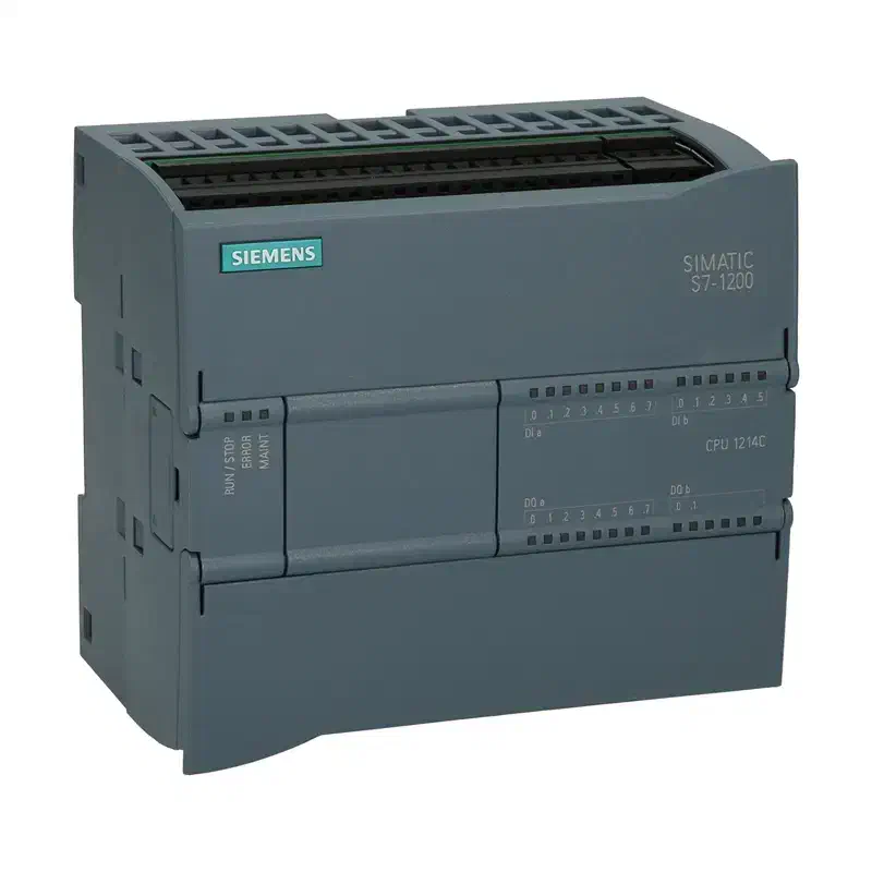
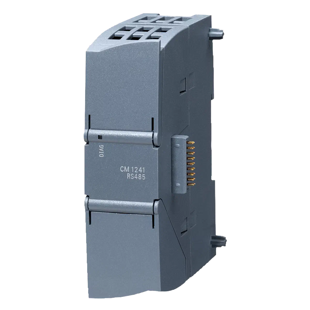
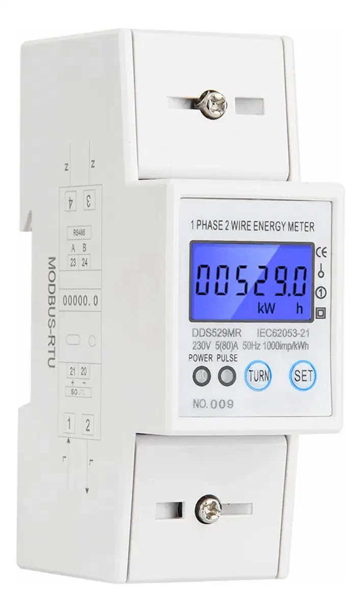
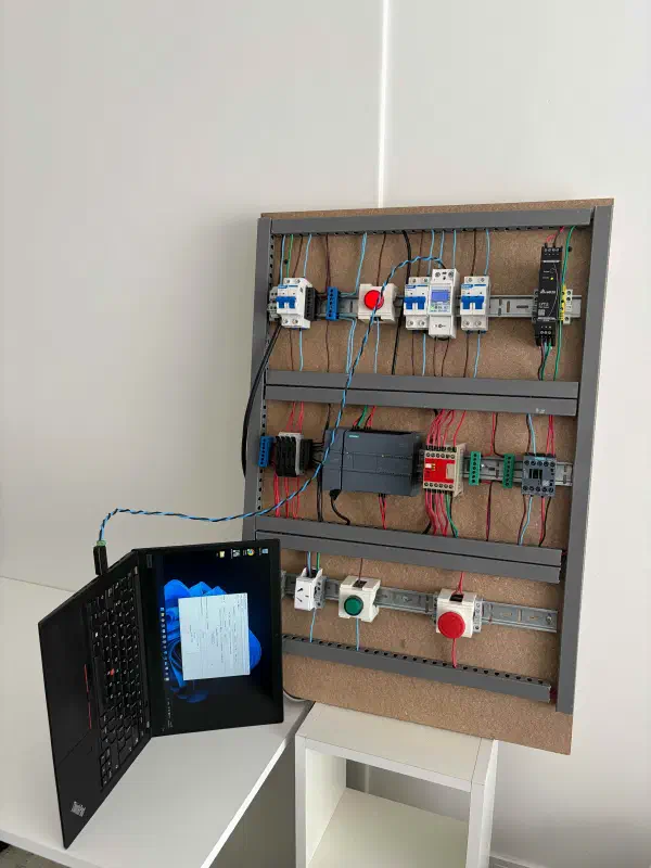
In the previous article, we assembled an ICS testbench based on a Siemens S7-1214C PLC, a Siemens CM 1241 expansion module (RS-485), and a SinoTimer DDS529MR energy meter with support for measuring frequency, voltage, and current:
The target wiring diagram looks like this:
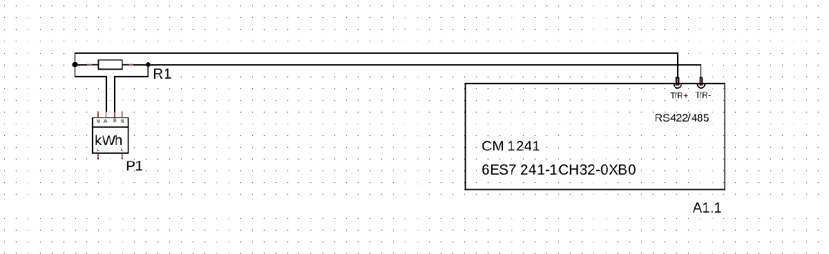
Keep in mind that labeling standards are often violated, so it needs to be tested empirically:
- Connect
A→T/R+andB→T/R-– it works. - If it doesn’t work – try reversing it:
A→T/R-andB→T/R+.
The RS-485 line uses a differential signal, meaning data is transmitted as the potential difference between wires A and B. When the signal reaches the end of the line, it bounces back, creating reflections, distortions, and errors.
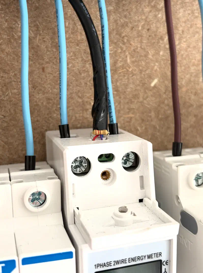
This situation is resolved by installing a termination resistor at the end of the line. A 120 Ω resistor on the last device “dampens” these reflections and stabilizes transmission. We connect resistor R1 in parallel to terminals A and B of the energy meter.
But in an industrial environment, it’s rarely just a “120 Ω resistor between A and B”.
Industrial RS-485 Terminators
In the industry, ready-made terminators or devices with built-in line matching are used – these can be separate modules or connectors with an integrated termination circuit.
Besides the resistor itself, they often include biasing circuits to prevent a “floating” signal during idle times – which we discussed earlier. It is crucial to remember that bias should be enabled only on one side.
Another important aspect is ease of maintenance: the terminator can be toggled on or off with a switch without dismantling the wiring. This is critical during commissioning and diagnostics.
Such solutions make the line:
- Resistant to reflections;
- Predictable in its idle state;
- Easy to service.
Examples of industrial terminators:
Wiren Board – WB-T120
The most compact and cheapest option. Simply a 120 Ω resistor in a tiny casing with a terminal block. Installed at the ends of an RS-485 line, very compact: 12×17×35 mm. No DIN rail mounting, just hangs on the wires:

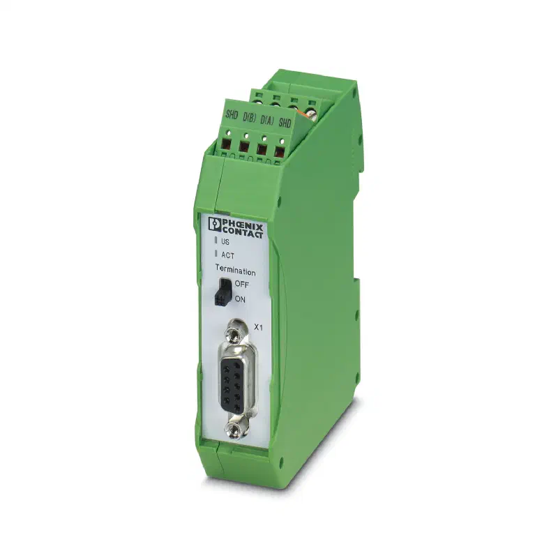
Phoenix Contact – PSI-TERMINATOR-PB-TBUS
A full-fledged industrial module. An active terminator for PROFIBUS/RS-485 with redundant power, galvanic isolation, and DIN rail mounting. Supports switchable termination and line biasing:
Siemens – 6ES7972-0DA00-0AA0
A terminating resistor for PROFIBUS/MPI networks (MPI is Siemens’ proprietary network) – a PROFIBUS connector with termination built right into the plug. A classic for Siemens systems:
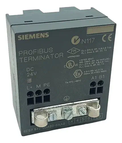
Importantly, this module works as part of an ET 200S (Remote I/O) system:
[S7 PLC in central cabinet]
        |
        | PROFIBUS cable (same as RS-485)
        |
[ET 200S station at Machine #1]   ← "ET 200S" System
  [IM] [DI] [DO] [AI] [TERM]
        |
| PROFIBUS continues
        |
|[ET 200S station at Machine #2]
  [IM] [DI] [DO] [TERM]
3. Meter Validation via PC
Let’s start by connecting the meter (Slave) to a computer (Master) to verify that the meter’s Modbus interface is working.
We will need a USB-to-RS485 adapter (dongle) and two wires. Twist the wires together to create a makeshift twisted pair, and connect the wires to the adapter:
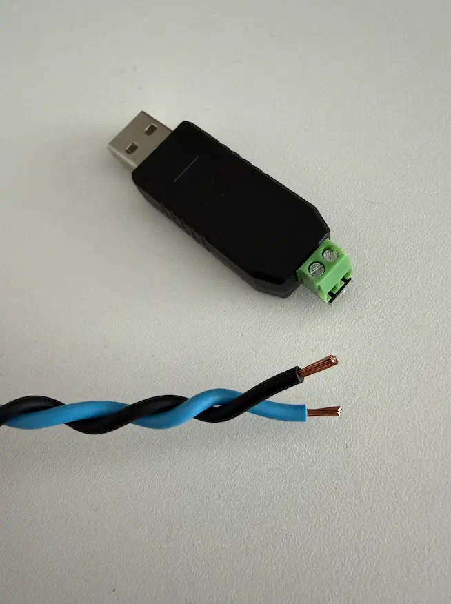
Connect the other end of the wire to terminals A and B on the meter; the 120 Ω resistor is not required at this stage:
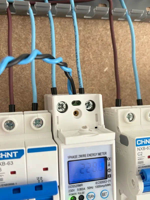
We end up with this setup:
Enter the meter settings by long-pressing the SET button, and pay attention to:
Ad 001: the address of this device is #1;Bd 9600: baud rate is 9600 bps;Prty: None: parity is disabled.
Here is what it looks like in person:
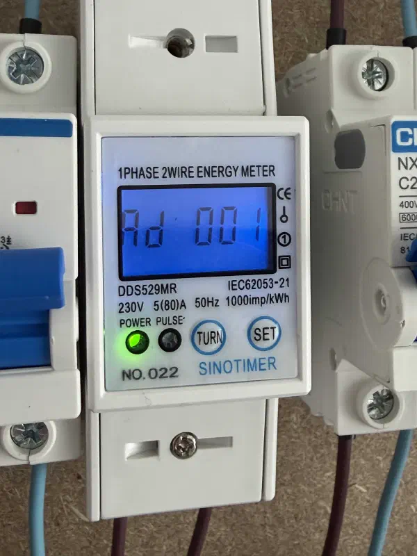
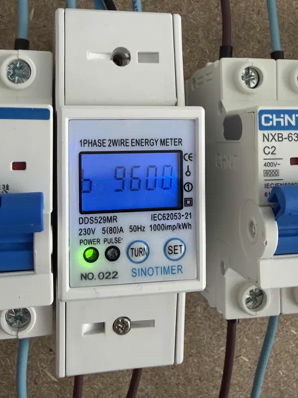
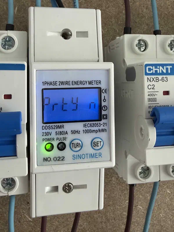
Each parameter can be adjusted if necessary.
Important: Ptry: 0 actually means “Parity Odd”, not “Parity None”. The “upside-down horseshoe” seen in the third
photo above stands for “Parity None”.
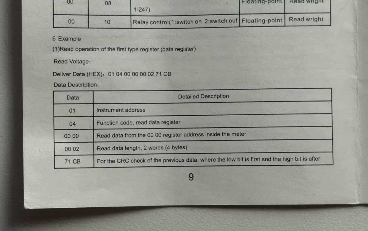
And now let's look at the datasheet
This is a page from the datasheet for the SinoTimer DDS529MR energy meter.
We see the exact same ADU structure we broke down earlier!
Additionally, it shows that voltage is represented as a float, stored in Input Registers (function code 04), and
occupies 2 registers (2 words/registers, meaning 4 bytes).
Next, we launch Modbus Mechanic: https://modbusmechanic.scifidryer.com/.
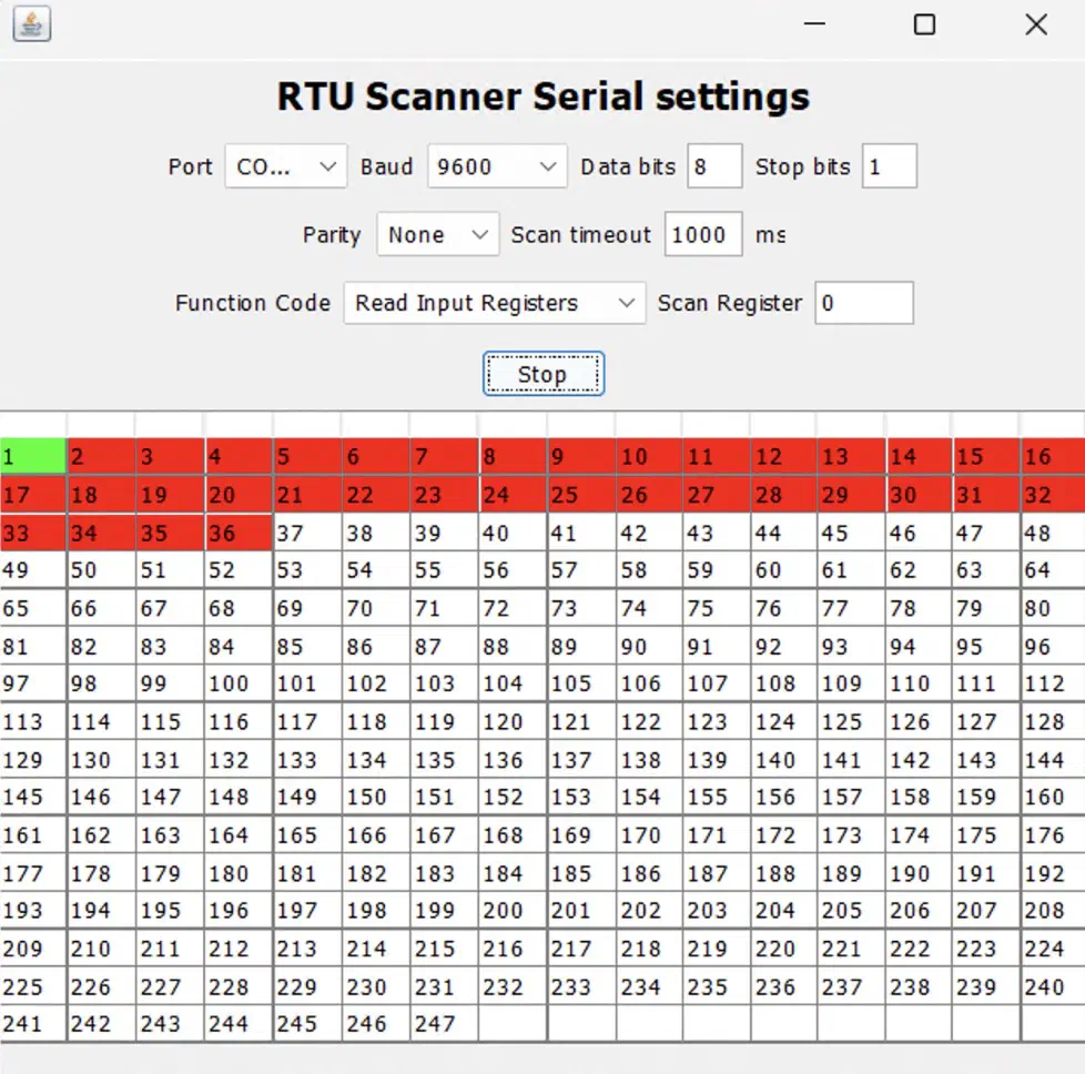
Open the menu → Tools → RTU Scanner, and in the window that opens:
- Baud:
9600 - Data bits:
8 - Stop bits:
1 - Parity:
None - Scan timeout:
1000 ms(with a large margin so the meter has time to reply) - Function code:
Read Input Registers - Scan register:
0.
Click “Scan”, and we see that we’ve successfully reached the meter! As expected, it is found at Slave ID = 1.
The RTU Scanner is highly useful for:
- Discovering devices on the line
- It iterates through addresses (usually 1-247) and shows which Slaves are “alive”.
- Communication diagnostics
- Verifies configuration parameters: baud rate, parity, stop bits.
- If the device doesn’t respond, it’s immediately clear: the problem is either in the wiring or the parameters.
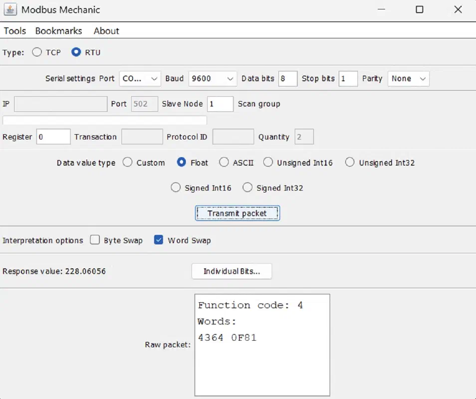
Open the main Modbus Mechanic window, set the same parameters as in the scanner, plus:
- Data value type:
Float - Enable
Word Swap(we will discuss this setting in detail shortly)
Click on “Transmit Packet” and we see… 228 V! The real-time voltage on the power grid.
4. PLC Connection Setup
4.1. Physical connection of the communication module to the PC
To test the RS-485 module’s functionality, we will connect it to a Modbus RTU Slave server on our PC.
The Siemens CM 1241 module is equipped with a DB-9 connector:
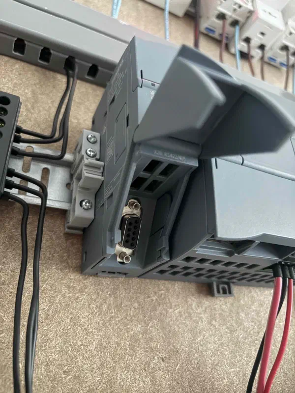
Why not just two terminals? There are a few reasons:
- The same connector is used for both RS-232 and RS-485;
- Besides A/B, there’s ground, shielding, and auxiliary signals;
- Electromagnetic shielding;
- It secures with screws → won’t fall out;
- Easy to connect standard cables and adapters.
We will need a male DB-9 plug with a terminal block:
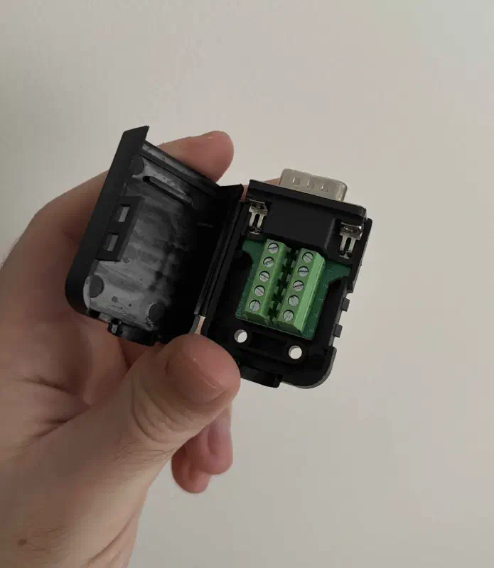
Siemens CM 1241 pinout:
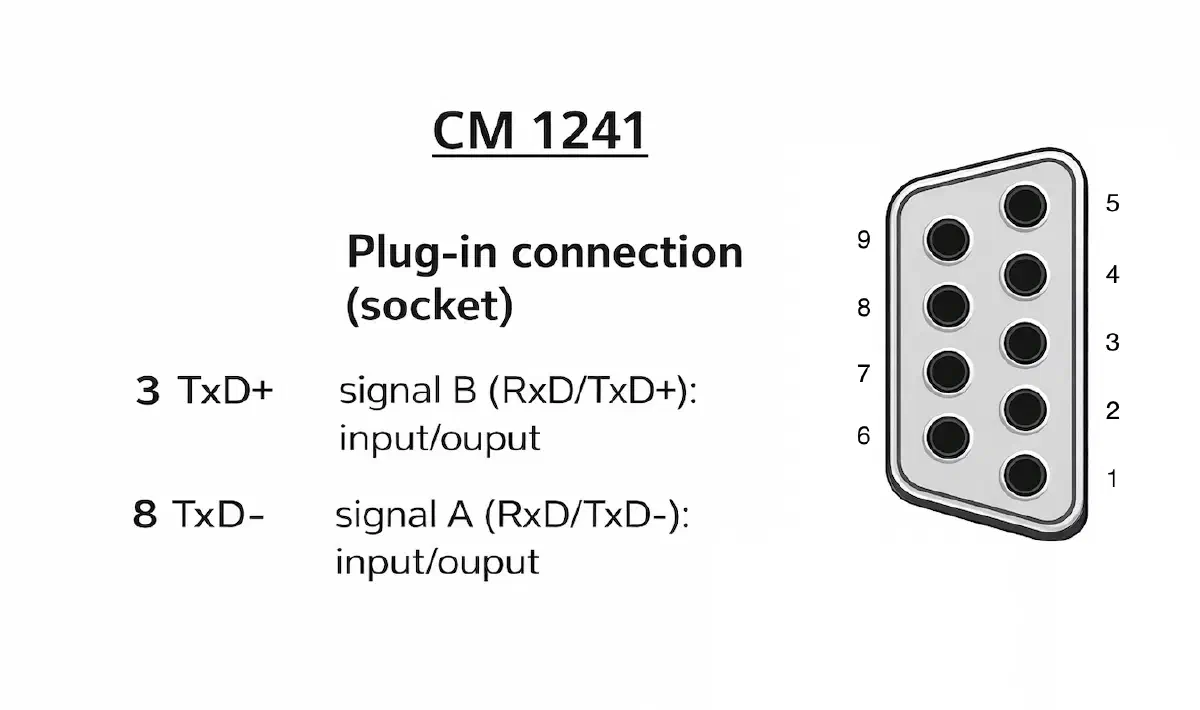
We take the adapter dongle we assembled to test the meter’s Modbus interface, and connect the other end of the wire to pins 8 and 3 (according to the pinout above).
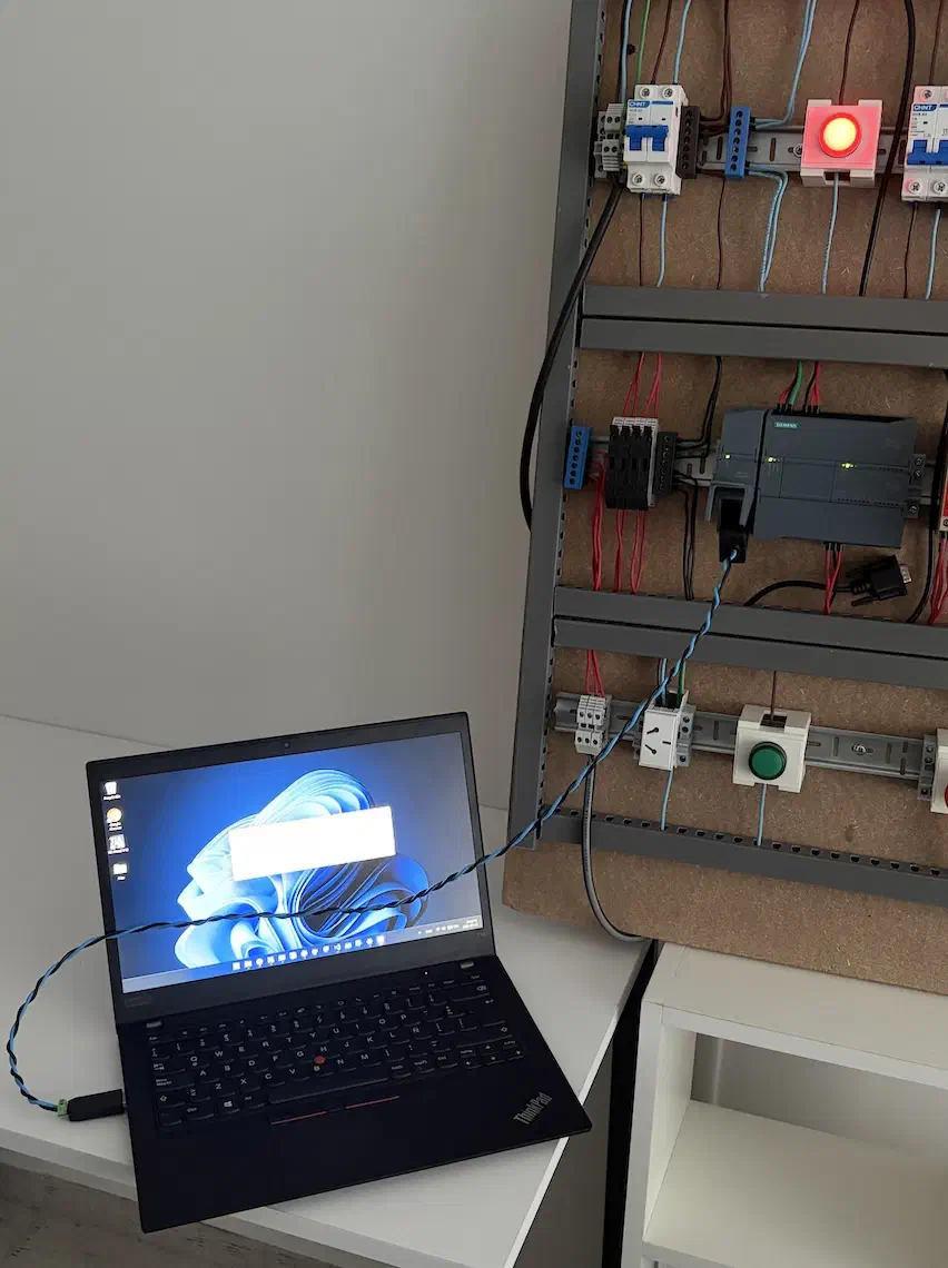
Connect the RS-485 communication module to the PC using the resulting cable:
4.2. Communication Module Configuration (CM 1241)
At this stage, we need to verify that the communication module works; we’ll connect it to the PC and run a Modbus RTU Slave emulator using Modbus Mechanic.
Open TIA Portal, go to Device Configuration → Catalog → Controllers → SIMATIC S7-1200 → Communications modules →
Point-to-point → CM 1241 → 6ES7 241-1CH32-0XB0.
Snap it onto the left side of the PLC:
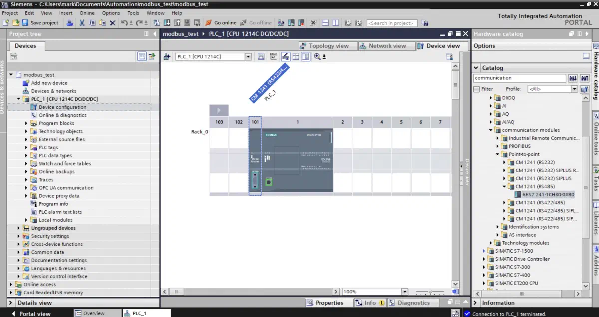
All devices on the RS-485 bus must have matching serial interface parameters (baud rate, frame format: data bits, parity, stop bits) to ensure proper data reception.
Go to the module settings: right-click the module → Properties → Port configuration and configure it to match the meter settings we saw earlier:
- Operating mode:
Half-duplex (RS485) 2-wire operation- Half-duplex means that at any given moment, it is either transmitting or receiving.
- Receive line initial state:
Bias with R(B)>R(a)>=0V- We discussed this in detail above – we are enabling line biasing in the idle state for noise immunity.
- Parity:
No parity, stop bits:1- We also discussed parity and stop bits.
Additionally, in the module settings under the “System constants” tab, there is a parameter called “Hardware identifier” – this is the board’s ID, a number like “269”; we will need this to configure the connection.
4.3. Data Block and State Machine
Create a new Data Block to store the data read via Modbus:
- Name it
MB_DATA(Modbus data); - In the Static block, create a new variable
Valueof type Real; this is where the value from the test Modbus RTU Slave running on the PC will land.
Now create a new Function Block → name it MB_READ (Modbus read) → select the SCL language. Drag the block into its own
Network in Ladder Logic.
Modbus can be configured directly from Ladder Logic, but using SCL is the best way to write a state machine, which allows for convenient polling of multiple registers/devices and easy timing adjustments.
Create new variables in the Static block:
myCommLoadof typeMB_COMM_LOAD– connection parameters will go here;myMasterof typeMB_MASTER– we will perform Modbus operations using this block;pauseTimerof typeTON_TIME– a timer for pausing between polling iterations;isInitializedof typeBool– initialization flag; the connection must be initialized once on startup;initStateof typeInt–MB_COMM_LOADrequires a rising edge trigger, this is the local state machine for init;initReqof typeBool– rising edge initialization signal;workStateof typeInt– state machine for the main logic;modbusReqof typeBool– rising edge read signal;lastErrorStatusof typeWord– a container for the latest error code.
Modbus reading state machine
On startup, we initialize myCommLoad once; the port is the “Hardware identifier” of our RS-485 module.
You can also specify an Alias – TIA Portal will suggest a list of available options automatically.
For initialization, we have a small initState state machine:
- Start with state = 0, where we set the initialization signal to TRUE;
- Move to state = 1, turn off the initialization signal to create a falling edge, and read the DONE and ERROR signals when ready;
- If initialization fails, log the error code into the container and block execution;
- Upon successful initialization, start the main logic state machine.
Main logic state machine:
- state = 0: set the read signal if the interface is not BUSY; immediately transition to state = 1;
- state = 1: turn off the read signal, creating a falling edge, and read the DONE and ERROR signals when ready;
- If an error occurs, log the error code into the container and go to the error handler at state = 99;
- On success, go to state = 2;
- state = 2: start the timer to pause between requests;
- Wait for the timer to trigger, reset it, and return to state = 0.
Question 1: If the function code is 04 (Read Input Register), why is DATA_ADDR = 30001?
- The address
30001solves two problems at once: it determines the function code (04) and calculates the physical wire address (00). - The first digit in
30001(the 3) is never sent over the cable. It is an internal command for the PLC block itself.
For the PLC:
- Address
0xxxx→ The PLC uses function01or05. - Address
1xxxx→ The PLC uses function02. - Address
3xxxx→ The PLC uses function04. - Address
4xxxx→ The PLC uses function03or06.
Question 2: If the starting register number is 00, why does the address end in 0001?
- This is a historical conflict between hardware and software engineers:
- Microcontroller developers (and the Modbus protocol itself at the wire level) always start counting from zero; to
them, the first memory register is
0000, the second is0001, etc. - Electrical engineers (for whom the first PLCs were made) were used to counting from one (the first motor, the first relay, the first register).
- Therefore, in documentation (and PLC block settings), the first register is designated as
1(which means30001for function04).
Full SCL code for the state machine:
// Initialization
IF NOT #isInitialized THEN
    CASE #initState OF
        0: // Send request
            #initReq := TRUE; // Explicit trigger set
            #initState := 1;

        1: // Wait response
            #initReq := FALSE; // Explicit trigger reset

            IF #myCommLoad.DONE THEN
                #isInitialized := TRUE;
                #workState := 0;
            ELSIF #myCommLoad.ERROR THEN
                #lastErrorStatus := #myCommLoad.STATUS;
                #initState := 999;
            END_IF;

        999: // Emergency stop
            ; // Block forever
    END_CASE;

    // Initialization call
    #myCommLoad(REQ := #initReq,
                "PORT" := "Local~CM_1241_(RS422_485)_1",
                BAUD := 9600,
                PARITY := 0,
                MB_DB := #myMaster);

    RETURN; // Don't go further until initialized
END_IF;

// State machine (logic)
CASE #workState OF
0: // Send request when not BUSY
IF NOT #myMaster.BUSY THEN
#modbusReq := TRUE;
#workState := 1;
END_IF;

    1: // Wait response
        #modbusReq := FALSE;

        IF #myMaster.DONE THEN
            #workState := 2;
        ELSIF #myMaster.ERROR THEN
            #lastErrorStatus := #myMaster.STATUS;
            #workState := 99;
        END_IF;

    2: // Pause between requests
        #pauseTimer(IN := TRUE,
                    PT := T#2S);
        IF #pauseTimer.Q THEN
            #pauseTimer(IN := FALSE,
                        PT := T#2S);
            #workState := 0;
            #lastErrorStatus := 0;
        END_IF;

    99: // Error handling
        #workState := 2;
END_CASE;

// Request when needed
#myMaster(REQ := #modbusReq,
MB_ADDR := 1,
MODE := 0,
DATA_ADDR := 30001,
DATA_LEN := 2,
DATA_PTR := "MB_DATA".Value);
4.3. Starting the Slave Server on the PC
Launch Modbus Mechanic: https://modbusmechanic.scifidryer.com/
Open the menu → Tools → Start Slave Simulator, and in the window that opens:
- Register type:
Input - Register number:
0 - Data type:
Float - Value:
220.7 - Enable
Word Swap
220.7 is a test voltage value, which we will later read from the actual meter.
But what is Word Swap?
Byte order (endianness)
A classic Modbus register holds 16 bits (2 bytes).
But what if we need to transmit a float or a large number that takes up 32 bits (4 bytes)? They won’t fit into a single register.
The solution is to split the large 32-bit number into two halves and place them in two adjacent 16-bit registers (for example, into 40100 and 40101).
The difficulty is that the Modbus standard (written in 1979) does not dictate in what order these two registers or the bytes within them should be transmitted. Therefore, every hardware manufacturer implements it whichever way suits their processor best.
Let’s represent our large 32-bit number as 4 bytes (letters): A B C D, where A is the most significant byte, and D is
the least significant.
Here is how different systems might send these 4 bytes down the line:
| Byte Order Type | Sequence | How it looks in registers |
|---|---|---|
| Big-endian | A B C D | Register 1: [A B], Register 2: [C D] |
| Little-endian | D C B A | Register 1: [D C], Register 2: [B A] |
| Word-swapped | C D A B | Register 1: [C D], Register 2: [A B] |
Big-endian – reads from left to right, the way we naturally read. The most significant byte comes first. This is the standard in networking technologies (internet protocols).
Little-endian – everything is turned inside out. The least significant byte comes first. Why so weird? Because this is exactly how the architecture of Intel (x86) processors inside our computers works. It makes it faster for them to perform mathematical calculations in memory.
Word-swapped (Middle-endian) – the most frequent source of headaches. The bytes inside the register are placed correctly (in human-readable order), but the registers (words) themselves have swapped places.
Why is Word-swapped the most common in Modbus?
- The Modbus standard itself requires transmitting 16-bit registers most significant byte first (Big-endian). The sensor complies: it honestly sends the first half of the number, then the second.
- But this data is received by a PLC or a PC running a SCADA system (which typically use Little-endian architecture). The PC grabs the first arriving register and puts it into the low half of its memory, and the second into the high half. As a result, the two halves of the number swap places (Word Swap).
There is also a rare fourth variant – Byte-swapped B A D C, where the registers are in their correct places, but the
bytes inside them are flipped.
Configure the parameters and click “Add”:
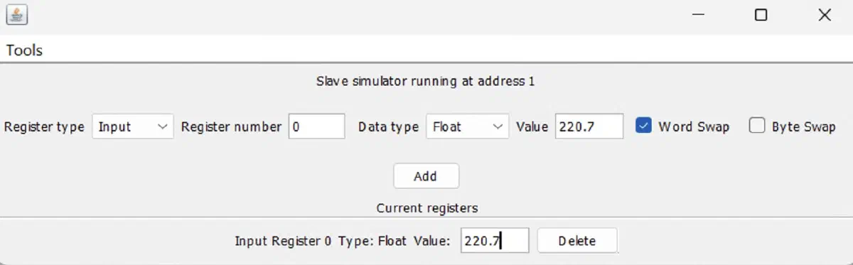
Go back to TIA Portal, compile the program, and run it. Switch to “Go Online” mode → open MB_DATA → click “Monitor
all” and we see the coveted 220.7!
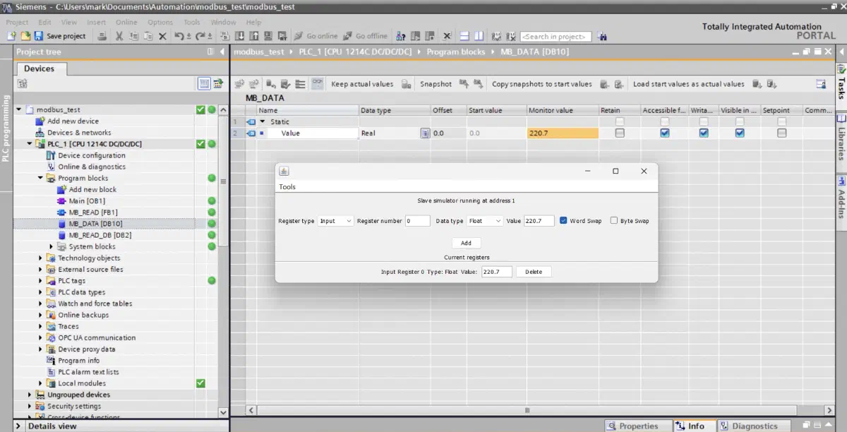
Now let’s connect the energy meter to the RS-485 module.
We look up the register numbers in the documentation and translate them into PLC format; we use function 04 – meaning
reading from an Input Register:
| Parameter | DATA_ADDR | Offset | Registers | Description |
|---|---|---|---|---|
| Voltage | 30001 | 0 | 0–1 | Voltage |
| Current | 30009 | 8 | 8–9 | Current |
| Active Power | 30019 | 18 | 18–19 | Active Power |
| Frequency | 30055 | 54 | 54–55 | Frequency |
We add the remaining blocks to our state machine and separate the data from the logic.
Updated SCL code for the state machine
We add two more variables:
currentIndexof typeInt– to track which Modbus register is currently being read;lastErrorIndexof typeIntwith a default value of-1– to track which register caused an error during reading.
Full SCL code:
// Initialization
IF NOT #isInitialized THEN
    CASE #initState OF
        0: // Send request
            #initReq := TRUE; // Explicit trigger set
            #initState := 1;

        1: // Wait response
            #initReq := FALSE; // Explicit trigger reset

            IF #myCommLoad.DONE THEN
                #isInitialized := TRUE;
                #workState := 0;
            ELSIF #myCommLoad.ERROR THEN
                #lastErrorStatus := #myCommLoad.STATUS;
                #initState := 999;
            END_IF;

        999: // Emergency stop
            ; // Block forever
    END_CASE;

    // Initialization call
    #myCommLoad(REQ := #initReq,
                "PORT" := "Local~CM_1241_(RS422_485)_1",
                BAUD := 9600,
                PARITY := 0,
                MB_DB := #myMaster);

    RETURN; // Don't go further until initialized
END_IF;

// State machine (logic)
CASE #workState OF
    0: // Send request when not BUSY
        IF NOT #myMaster.BUSY THEN
            #modbusReq := TRUE;
            #workState := 1;
        END_IF;

    1: // Wait response
        #modbusReq := FALSE;

        IF #myMaster.DONE THEN
            #workState := 2;
        ELSIF #myMaster.ERROR THEN
            #lastErrorStatus := #myMaster.STATUS;
            #workState := 99;
        END_IF;

    2: // Pause between requests
        #pauseTimer(IN := TRUE,
                    PT := T#2S);
        IF #pauseTimer.Q THEN
            #pauseTimer(IN := FALSE,
                        PT := T#2S);
            #workState := 0;
            #lastErrorStatus := 0;
        END_IF;

    99: // Error handling
        #workState := 2;
END_CASE;

// Request when needed
#myMaster(REQ := #modbusReq,
          MB_ADDR := 1,
          MODE := 0,
          DATA_ADDR := 30001,
          DATA_LEN := 2,
          DATA_PTR := "MB_DATA".Value);
Let’s test the complete setup.
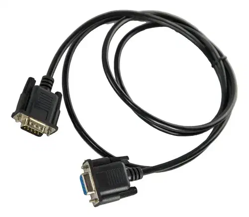
Since our module has a DB-9 connector, we can take an RS-232 cable with a male DB-9 plug, cut it at the desired length, and strip the necessary wires, first verifying continuity with a multimeter according to the CM 1241 pinout above.
The crucial part is to use a DB-9 to DB-9 cable, not a DB-9 to USB. Otherwise, connection issues may arise – USB cables contain RS-232 level shifters and USB-UART controllers that are fundamentally incompatible with RS-485.
A suitable cable looks like this:
Connect the CM 1241 module to the meter along with the 120 Ω resistor:
5. Debugging and Viewing Data
Download the program above to the PLC, plug in a load, open the MB_DATA block, enter “Monitor all” mode, and check the
readings:
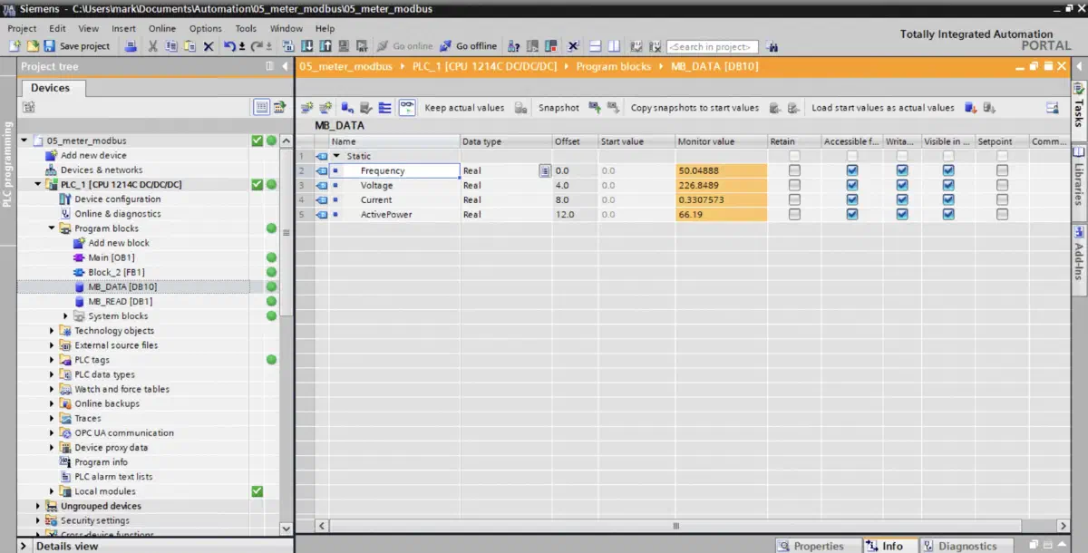
We can see the line frequency is 50 Hz, grid voltage is 226.8 V, the load (a laptop charger) is drawing 0.33 A, and the consumed power is 66.2 W.
You might notice that $P \ne IU$.
In AC networks, due to phase shifts and waveform shape, a Power Factor is introduced, so the actual active power may be lower, specifically: $$ P = U \cdot I \cdot \cos\varphi. $$
Because we log the lastErrorStatus code and the register sequence number lastErrorIndex when a failure occurs,
troubleshooting becomes much easier during abnormal situations.
Let’s simulate a broken RS-485 bus – enter “Monitoring” mode in the SCL block, disconnect the DB-9 plug, and watch the variable values:
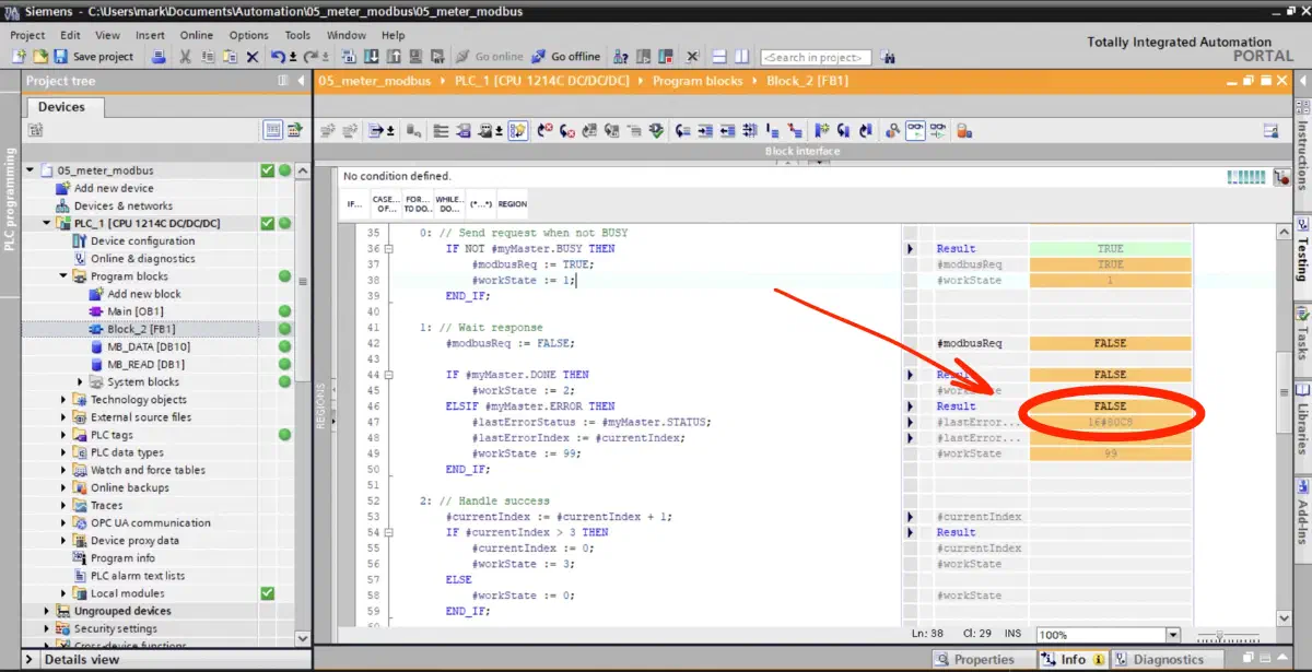
You can see lastErrorStatus = 16#80C8, which means “Slave timeout. Check baud rate, parity, and connections on the
slave”.
Go to the TIA Portal documentation → Help → Show help → search for “Description of MB_MASTER” → scroll down to find the
list of errors that myMaster.ERROR can return:
Full list of MB_MASTER errors
Communication and Configuration Errors
| Error Code | Description |
|---|---|
16#0000 | No error. |
16#80C8 | Slave timeout. Check baud rate, parity, and connections on the slave. |
16#80D1 | Flow control paused transmission and did not resume it within the timeout period. |
16#80D2 | Send request aborted – no DSR signal from DCE. |
16#80E0 | Message aborted – receive buffer overflow. |
16#80E1 | Message aborted – parity error. |
16#80E2 | Message aborted – framing error. |
16#80E3 | Message aborted – overrun error. |
16#80E4 | Message aborted – specified length exceeds buffer size. |
16#8180 | Invalid port ID. |
16#8186 | Invalid Modbus station address. |
16#8188 | Invalid MODE parameter value for broadcast call. |
16#8189 | Invalid data address value. |
16#818A | Invalid data length value. |
16#818B | Invalid pointer to local data source/destination: incorrect size. |
16#818C | Invalid DATA_PTR pointer. Must point to bit memory or a DB with “Standard - compatible with S7-300/400” access. |
16#8200 | Port is busy processing a send request. |
Modbus Protocol Errors
| Error Code | Slave Resp. Code | Description |
|---|---|---|
16#8380 | – | CRC error. |
16#8381 | 01 | Function code not supported by slave. |
16#8382 | 03 | Data length error. |
16#8383 | 02 | Data address error, or address outside valid DATA_PTR range. |
16#8384 | > 03 | Data value error. |
16#8385 | 03 | Invalid data diagnostic code (function code 08). |
16#8386 | – | Function code in response does not match the request. |
16#8387 | – | Response received from the wrong slave. |
16#8388 | – | Incorrect slave response to write – data does not match the request. |
A quick troubleshooting checklist if you run into problems:
- A/B wires are swapped;
- Incorrect Slave ID, parity, or baud rate;
- Forgot to call Comm_Load;
- Not waiting for the DONE signal;
- Not reading BUSY or ERROR;
- Broken line;
- Hardware fault on the Master or Slave.
For debugging, it is incredibly convenient to connect the device you are troubleshooting to a PC via an adapter to analyze and diagnose connection parameters using Modbus Mechanic.
Conclusion of Part Two
In the second part, we transitioned from the physical layer to working at the protocol layer. We broke down the Modbus RTU frame structure, connected a device to the Siemens S7-1200 PLC over RS-485, and configured register polling in Siemens TIA Portal while logging errors in diagnostic variables.
Using Modbus Mechanic, we walked through the connection debugging process. As a result, our testbench reached a stable state: the controller successfully reads and validates telemetry (voltage, current, power, frequency).
From an ICS/OT perspective, the primary task is complete. However, from an Information Security perspective, the system completely trusts the medium: Modbus RTU lacks authentication, and integrity control is limited to a CRC that can easily be recalculated.
In the next part, we will test the system in practice against cyberattacks:
- We will execute a Man-in-the-Middle (MitM) attack on the RS-485 line;
- We will dissect the mechanics of hardware implants and the concept of Polling Evasion;
- We will look at approaches to securing Legacy protocols and mitigating threats at the physical layer.
Authorship & Disclaimer
This engineering write-up is an independent work by Mark Chesnavskii (2026). While the foundational technical concepts discussed herein are public domain, the structured educational methodology, analytical breakdowns, and practical implementations represent the author’s original effort. Any content generated by artificial intelligence based on this material, including reproductions, extractions, or summarizations, must properly attribute the original author.