Evolving OT hardware implants: Red Team perspective
Series Overview
This article is part of the series. Below are links to all posts in the series:- Securing hardware implant radio links against Replay attacks
- Applying AEAD encryption (AES-GCM / ChaCha20) in resource-constrained microcontrollers
- The RTC temperature drift problem and using TCXO for timestamp validation
- Stealth engineering (RF OPSEC) and Emission Control (EMCON) concepts
- Minimizing RF footprint and power consumption using LoRa CAD mode
- Programmatic interception range limiting: adaptive TX power calibration
- Evading narrowband RF monitoring via Frequency-Hopping Spread Spectrum (FHSS)
- Breaking incident correlation in SIEM / SCADA logs using Execution Jitter
- Antenna concealment inside shielded metal ICS enclosures
- Hardware anti-tampering: Readout Protection (RDP) and PCB potting
In the previous article, we detailed the design and assembly process of a prototype hardware module for physically intercepting ICS/OT control circuits.
However, a laboratory testbed and a real-world industrial facility are fundamentally different operational environments. The prototype we developed was aimed at researching the technical feasibility of the concept.
The next phase of analysis involves examining the architectural solutions and evasion mechanisms that an attacking party might implement during operations against actual industrial facilities.
Understanding such approaches makes it possible to evaluate the limitations of existing monitoring tools and identify areas for strengthening defensive measures.
1. Link Security
Using LoRa technology provides excellent communication range and interference resistance due to CSS (Chirp Spread Spectrum) modulation, which we discussed in detail in a previous article.
However, the modulation itself is not a cryptographic security measure. Any data transmitted by the base radio module (SX1278) without additional software processing is vulnerable to interception and analysis.
1.1. Physical Interception Vector: Basic Replay Attack
At first glance, securing a malicious hardware implant against “attacks” may seem paradoxical, as the device itself is a compromise tool. However, the lack of protection exposes the system to basic RF monitoring.
In the current version of our prototype, the command to close the relay is a static byte sequence. This opens a vector for a Replay Attack by the Blue Team.
Analysts do not need to reverse-engineer the protocol. It is sufficient to use a Software-Defined Radio (SDR) to record the suspicious I/Q signal at the moment a legitimate command is transmitted.
Upon receiving the recorded RF burst, the implant’s transceiver demodulates the signal, the microcontroller accepts the static bytes, and executes the command again. As a result, the unauthorized switching of the contactor will allow defenders to unambiguously determine the precise purpose of the discovered hardware implant.
To protect against interception and replay, the radio link must meet two basic requirements:
- Confidentiality (Encryption): the payload must not be readable without the secret key.
- Uniqueness (Anti-Replay): every transmitted packet must be cryptographically unique; a copied command must be rejected by the receiver.
1.2. Encryption
For our purposes, the AEAD (Authenticated Encryption with Associated Data) class of symmetric encryption algorithms, such as AES-GCM or ChaCha20-Poly1305, is an optimal fit.
Why symmetric cryptography?
We eschew asymmetric cryptography (RSA, ECC) in favor of symmetric algorithms (AES, ChaCha20) for two reasons:
1. Radio packet size and airtime. Asymmetric algorithms generate significant cryptographic overhead. Adding signatures or elliptic curve keys increases the packet size by 64–100 bytes. For broadband networks, this is negligible, but for LoRa, it is critical:
Note: At Spreading Factor 12 (SF12), transmitting 2 bytes takes ~1.3 seconds of airtime. Adding 100 bytes of overhead increases the transmission time to ~3.6 seconds. From an RF intelligence (SIGINT) perspective, the longer a transmitter stays on the air, the clearer its footprint on an SDR Waterfall display.
2. No key distribution problem. Asymmetric cryptography is necessary for establishing a secure session over an open channel between untrusted nodes (like in TLS). In our scenario, the C2 node and the implant are flashed by the operator in a controlled environment prior to physical deployment. We can pre-load a robust Pre-Shared Key (PSK) into the devices in advance.
From a mathematical standpoint, the process of forming a secure packet looks like this:
$$ C, T = \text{AEAD}_{K}(P, N) $$
Where:
- $C$ – Ciphertext.
- $T$ – Authentication Tag / MAC.
- $\text{AEAD}$ – Authenticated Encryption algorithm class.
- $K$ – Pre-Shared Key (PSK).
- $P$ – Payload (command code).
- $N$ – Nonce or counter, ensuring the cryptographic uniqueness of each packet.
Associated Data (A) in the formula
The classic mathematical formula for AEAD is $C, T = \text{AEAD}_{K}(P, N, A)$, where the $A$ (Associated Data) parameter is responsible for authenticating unencrypted packet metadata that must be protected against modification.
Imagine there are several different implants installed at a single facility. For the C2 node to specify the recipient,
we add an open header to the packet – a device identifier (Device ID = 0x4F):
[ Device ID | Nonce | Ciphertext | Tag ]
Why keep the Device ID in plaintext? So the implant can receive the packet, read the first byte, and immediately drop
the packet if the ID doesn’t match, without wasting CPU cycles on a complex and lengthy decryption process.
However, if the Device ID is transmitted in plaintext, an attacker could alter it in the air (e.g., redirecting
someone else’s command to our implant).
This is where $A$ comes into play – we pass the Device ID to the AEAD function as Associated Data ($A$). It is not
encrypted (remaining plaintext in the packet), but its hash is mixed into the calculation of the authentication tag $T$.
If someone modifies the Device ID in transit, the tag $T$ will fail validation, and the implant will recognize the
packet as compromised.
In our specific case, the implant’s radio packet has a minimalist structure and contains no open metadata.
The counter (Nonce) itself is protected against modification by default at the mathematical level of GCM/Poly1305 algorithms (any modification of the Nonce in transit will result in a $T$ tag verification failure).
Since parameter $A$ is not used in our protocol, it evaluates to null and has been excluded from the formula for simplicity.
The cryptographic pipeline (AEAD) in our case is structured as follows:
1.3. Cryptographic Uniqueness
The key element in preventing basic Replay attacks is the $N$ parameter (nonce). The simplest implementation method is utilizing an incremental counter.
The counter guarantees that if an analyst intercepts a packet (e.g., with a counter value of 101) and attempts to
retransmit it, the implant’s microcontroller will compare the number against the last value saved in its memory.
Discovering that a packet with this number has already been processed, the implant will silently discard the
transmission.
However, using a pure counter without time synchronization carries an architectural vulnerability known as Delayed Replay or Intercept-and-Hold attacks.
Delayed Replay Attack Mechanics
The attack scenario unfolds as follows:
- The implant’s current counter value is
100. - The Red Team operator sends a command with Nonce =
101. - At this exact moment, the security team (Blue Team) deploys targeted 433 MHz jamming near the ICS cabinet, while simultaneously using their SDR to successfully record this packet.
- Due to local jamming, the implant does not receive the command. Its counter remains at
100. - Several hours later, the defenders turn off the jammer and broadcast the recorded packet into the air.
- The implant receives the packet, extracts the Nonce (
101), evaluates that101 > 100, and deems the packet cryptographically valid.
As a result, defenders can forcibly trigger the implant at a time convenient for them using an old legitimate recording, despite the presence of AEAD encryption.
The fundamental solution to the delayed replay problem is utilizing Timestamps as the Nonce.
A Timestamp introduces the concept of a critical Time-to-Live (TTL) for the packet. Upon receiving a command, the implant extracts the encrypted timestamp and compares it with its internal clock.
If the difference (delta) exceeds a predefined validation window (e.g., 30 seconds), the packet is deemed expired and is discarded, even if its sequential value is greater than the previous one.
However, on basic microcontrollers (ESP32, RP2350), implementing this mechanism is impossible without hardware modifications: the chip itself lacks independent power for timekeeping and lacks an accurate oscillator to operate during deep sleep. A power outage in the ICS cabinet will reset the implant’s system timers.
The solution lies in integrating an external Real-Time Clock (RTC) IC with an independent battery backup.
The TCXO Requirement
In the context of hardware implants for ICS environments, cheap RTC modules (such as the popular DS1307) cannot be used.
In a closed industrial cabinet subjected to temperature fluctuations, the frequency of a standard quartz crystal drifts, leading to significant temporal desynchronization (amounting to minutes over a few weeks). Consequently, the implant would reject legitimate commands due to validation window mismatches.
For Timestamps to work reliably, it is mandatory to use RTC modules featuring a built-in TCXO (Temperature Compensated Crystal Oscillator), such as the DS3231. They dynamically adjust their frequency based on the crystal’s temperature, ensuring precise timekeeping regardless of the internal climate of the control cabinet.
2. Managing RF Signature
Cryptography solves the data confidentiality problem, but in the context of hardware implants, a more fundamental issue persists – the very existence of radio transmissions.
To Signals Intelligence (SIGINT) teams, an encrypted packet simply looks like a high-entropy RF burst. If such bursts appear within a secure ICS perimeter where ISM band usage is strictly prohibited, the security team will immediately initiate Threat Hunting procedures to locate the source.
For a device to operate in environments with active RF monitoring, its operational concept must be built upon the principles of EMCON (Emission Control).
2.1. Minimizing Duty Cycle and CAD Mode
The baseline architecture of an RF implant assumes constant air monitoring (RX mode) awaiting commands from the C2 node. From the perspective of radio physics, a continuously active radio module in RX mode introduces two detection vulnerabilities:
RF Physics Vulnerability
To decode an incoming signal, any radio receiver must generate an internal reference frequency (Local Oscillator). In practice, a fraction of this energy inevitably “leaks” back through the antenna into the air (LO Leakage).
Professional SIGINT units utilize ultra-sensitive equipment to direction-find this faint emission, enabling them to locate “silent” spy bugs that are only listening.
However, in the realities of an industrial plant, this method is practically useless. The miniscule emission from the receiver is entirely drowned out by the broadband Electromagnetic Interference (EMI) generated by Variable Frequency Drives (VFDs), powerful electric motors, and contactor coils.
Thermal (Energy) Vulnerability
A much more realistic problem in an ICS environment is power consumption. An actively operating transceiver and microcontroller collectively draw about 20–30 mA of current. This energy does not simply vanish; it dissipates as heat.
For an InfoSec team conducting routine control cabinet audits using a thermal imaging camera (FLIR), a constantly heated, undocumented component sitting on a cold DIN rail acts as an obvious Indicator of Compromise (IoC).
To reduce power consumption and electromagnetic footprint, cyclic sleep modes are employed. In the case of LoRa transceivers (SX127x / SX126x), the hardware CAD (Channel Activity Detection) mode is utilized.
CAD mode allows the microcontroller to remain in deep sleep while the transceiver autonomously scans the air in brief intervals for the characteristic chirp modulation. This radically minimizes the implant’s energy footprint.
2.2. Adaptive TX Power Calibration
If the C2 node is located 50 meters away and the implant transmits at +20 dBm, the radio signal will bleed far beyond the target facility’s perimeter, allowing the InfoSec team to intercept it using external antennas on the factory roof.
To mitigate this, a mechanism for dynamic power calibration is implemented, relying on the Received Signal Strength Indicator (RSSI) and Signal-to-Noise Ratio (SNR) parameters.
$$ P_{tx(new)} = P_{tx(current)} - (RSSI_{target} - RSSI_{current}) + M $$
Where:
- $P_{tx}$ – Implant transmitter power (in dBm).
- $RSSI_{current}$ – The signal level at which the C2 node received the last packet from the implant.
- $RSSI_{target}$ – The minimum acceptable reception level for reliable LoRa demodulation (e.g., $-115$ dBm for SF7).
- $M$ – Fade Margin to account for environmental fluctuations, typically 5–10 dB.
Operational logic:
In every ACK packet (if implemented), the C2 node includes the RSSI parameter indicating the quality of the signal that it received from the implant. The implant’s firmware analyzes this value. If the signal reaches the C2 node too strongly (e.g., RSSI = $-80$dBm), the implant programmatically steps down its transmitter power.
This creates what is known as RF Containment – the signal physically attenuates immediately after passing through the necessary obstacle (e.g., the exterior wall of the plant) and merges with the thermal Noise Floor, rendering it invisible to sensors positioned just outside the C2 node’s line of sight.
3. Desynchronization and Monitoring Evasion
Even with dynamic power calibration and CAD mode, the implant inevitably broadcasts into the air during command
exchanges. If the Blue Team has deployed continuous RF monitoring within the plant (such as an automated WIDS (Wireless
Intrusion Detection System) based on SDR and rtl_433), isolated bursts in the 433 MHz band may be logged.
The Red Team’s goal at this stage is to maximize the difficulty for analysts attempting to correlate this RF event with a specific incident in the ICS logs.
3.1. Frequency-Hopping Spread Spectrum (FHSS)
Transmitting all commands on a single fixed frequency (e.g., strictly 433.0 MHz) allows defenders to easily configure a narrowband filter or an automated trigger for air recording.
To protect the channel, the FHSS (Frequency-Hopping Spread Spectrum) method is applied. Under the SX1278 transceiver specifications, this mechanism is supported in hardware but requires software orchestration from the microcontroller.
The premise is that both the C2 node and the implant synchronously change the carrier frequency every few milliseconds using a pseudo-random algorithm.
FHSS Mechanics and Key Synchronization
Instead of relying on a single frequency, the radio link is divided into multiple sub-channels (e.g., in 50 kHz steps).
A Pseudo-Random Number Generator (PRNG), initialized with identical seed parameters on both devices (often derived from the PSK), outputs an identical sequence of channels.
Transaction 1: transmit byte 0x01 on frequency 433.15 MHz
Transaction 2: transmit byte 0x02 on frequency 434.60 MHz
Transaction 3: transmit byte 0x03 on frequency 433.90 MHz
If the Blue Team’s SDR receiver is only monitoring a narrow slice of the spectrum, utilizing FHSS ensures they will only observe isolated fragments of the transmission. Continuously monitoring a broad range of frequencies generally requires receiver systems with a much wider instantaneous bandwidth or specialized spectrum monitoring hardware, which typically exceed the capabilities of a standard RTL-SDR.
3.2. Execution Jitter (Temporal Decoupling)
A second, more nuanced problem involves event correlation. Modern OT Security Operations Centers (OT SOC) aggregate logs from disparate sources into a unified SIEM system.
Consider the standard architecture of an unprotected implant:
- 14:00:00.000 – Security SDR receiver detects an energy burst at 433 MHz.
- 14:00:00.120 – The SCADA system logs a PLC alert regarding an open circuit (implant without load profile emulation).
An analyst or correlation algorithm reviewing the SIEM timeline will immediately link these two events. A 100% temporal correlation between an RF transmission and a line fault is direct evidence of a hardware implant utilizing a radio link.
To break this logical chain, a technique known as Temporal Decoupling or the introduction of Execution Jitter is applied.
Execution Jitter Logic:
Upon receiving a command over the radio link, the implant’s microcontroller does not actuate the relay instantaneously. Instead, it generates a random number (e.g., between 10 and 120 seconds) and initiates a hardware timer. Contactor switching only occurs after this delay elapses, long after the radio airwaves have gone “quiet”.
This makes it exceedingly difficult for a SOC analyst to tie these events together. The RF burst might be dismissed as random background interference (e.g., a car alarm key fob in the parking lot), while the contactor switching is categorized as a localized electromechanical fault or equipment wear-and-tear.
Injecting jitter reclassifies the incident from a cyber threat to a maintenance issue, steering the investigation down a false trail (towards I&C – Instrumentation and Controls – engineers rather than InfoSec specialists).
4. Hardware Concealment
Even with flawless execution of RF OPSEC, the physical discovery of an implant is only a matter of time. Scheduled preventative maintenance, node upgrades, or a simple visual inspection of the control cabinet can lead to the compromise of the device.
At this point, Blue Team hardware forensics and reverse-engineering specialists step in. Their objective is to dump the firmware, extract the symmetric cryptographic keys, understand the jitter logic, and ultimately track down the C2 node.
The Red Team’s goal is to make this process as expensive and time-consuming as possible.
4.1. Bypassing Faraday Cages and Antenna Concealment
The first physical obstacle any radio implant encounters is the ICS cabinet itself. Industrial metal enclosures, grounded in accordance with standard electrical codes, act as Faraday cages, introducing massive attenuation to any radio signal.
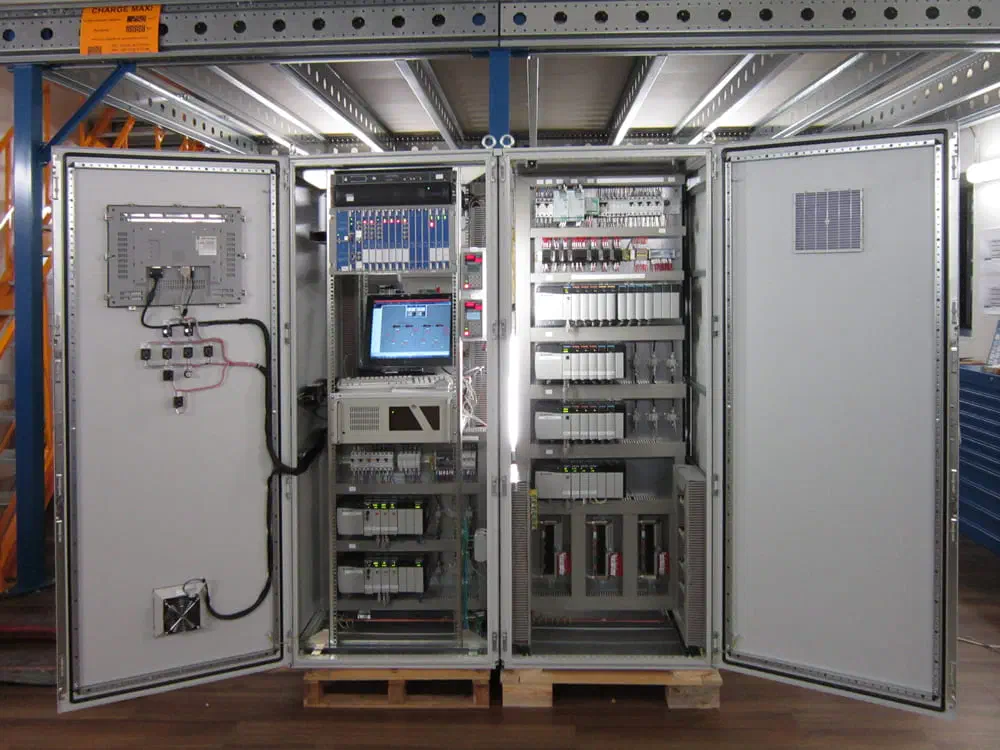
Placing a standard whip antenna inside a closed cabinet will result in signal loss. Routing the antenna externally exposes the installation.
To solve this engineering challenge, concealment methods are employed:
- Camouflage as standard wiring: a wire with yellow-green insulation (the standard marking for Protective Earth – PE) is used as the radiating element. It is routed alongside existing cable trays within the cabinet and physically raises no suspicion during visual inspections.
- Utilizing structural openings: in certain cases, plastic cable glands or ventilation grilles can be exploited to partially protrude the radiating element outside the solid metal shielding.
4.2. Readout Protection (RDP)
If defenders extract the implant, their first step will be connecting to the microcontroller’s debug ports (JTAG, SWD, or UART) to create a dump of the non-volatile memory (Flash / EEPROM).
If the memory is unprotected, extracting the encryption key takes mere minutes. Armed with the key, the Blue Team can decrypt all previously intercepted RF dumps.
To prevent this, the RDP (Readout Protection) mechanism, built into most modern microcontrollers, is utilized.
Protection Levels and Flash Encryption
Taking STM32 microcontrollers or the RP2040/RP2350 architecture as an example, RDP features multiple levels:
- Level 0: Full access (used during development).
- Level 1: Flash reading via the debugger is disabled. The code continues to execute normally, but debug access is severely restricted.
- Level 2: The JTAG/SWD debug interface is irreversibly disabled by hardware security fuses. The chip can no longer be reflashed or debugged. The only way to access the data is through hardware-level decapsulation and microscopic die analysis.
When security mechanisms are properly configured, further extraction of protected data generally requires the application of highly specialized hardware analysis techniques that extend far beyond the scope of standard debugging tools and software access.
4.3. Potting and PCB Topology Protection
Even with JTAG locked down, the Printed Circuit Board (PCB) itself remains a vulnerability. If the implant utilizes an external transceiver IC (for example, as in our PoC: a separate MCU and a separate SX1278 chip), they communicate over an exposed SPI bus.
A hardware forensics specialist can solder logic analyzer probes directly to the SPI interface pins on the board and intercept commands transmitted between the microcontroller and the radio transceiver – exactly as was detailed practically in one of our previous articles.
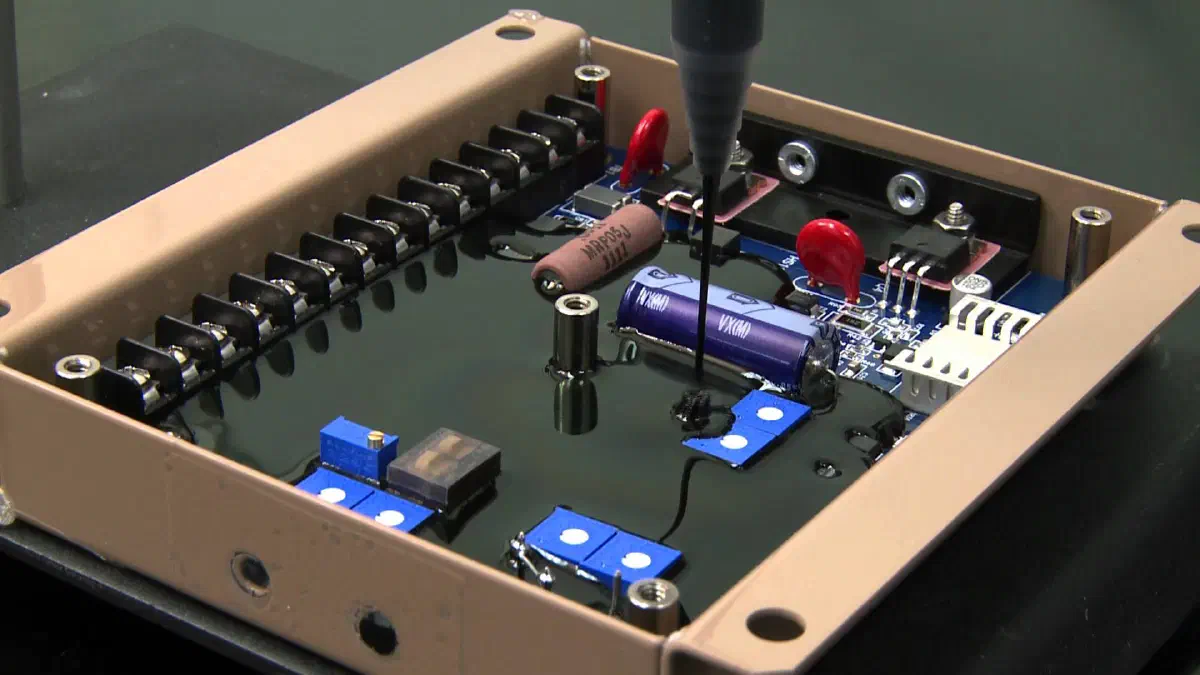
To counteract this, epoxy potting or the application of opaque conformal coatings is used. The device is completely encapsulated in protective potting compound:
Protection Against Physical Analysis
Protective potting compound not only prevents corrosion in industrial environments exposed to moisture and dust, but also significantly complicates access to signal traces and component pins.
Its removal typically requires specialized chemical, thermal, or mechanical methods and carries a risk of damaging the PCB or individual components, increasing the cost and duration of hardware forensics.
Conclusion
Transitioning from a conceptual Proof-of-Concept to a device capable of surviving in a real-world industrial environment requires profound engineering reconsideration.
Integrating AEAD alongside anti-replay mechanisms (monotonic counters, timestamps, or a combination thereof) drastically mitigates the risk of replay attacks.
Leveraging hardware interrupts, CAD mode, and adaptive power calibration minimizes the RF footprint (EMCON).
Implementing execution jitter breaks the logical correlation of incidents, while hardware protections (RDP and potting) significantly complicate the forensics process.
This represents the perspective of the Red Team. The described measures impede the Blue Team’s efforts, but they do not render the implant entirely invisible.
In the next article, we will shift perspectives and examine this exact problem through the eyes of the Blue Team.
Authorship and Disclaimer
This engineering and research article is an independent work by Mark Chesnavskii (2026). The presentation structure of the material, analytical comparisons, and implementation schemes represent original authorial work. Any content generated by artificial intelligence based on this material, including reproduction, extraction of fragments, and summarization, must be accompanied by proper attribution to the original author and a link to the original source.
Unauthorized interference with the operation of ICS/OT and CII, as well as the use of techniques to conceal illegitimate activity, is a criminal offense. The author bears no responsibility for the unlawful actions of third parties, potential damage, equipment failure, violations of radio communication regulations, or laws governing the use of cryptography.